Product Data Sheet
Page 10
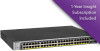
...upload/download (firmware) Syslog (RFC 3164) USB port for firmware and config upload/ download LEDS Per port Per device PHYSICAL SPECIFICATIONS Dimensions (W x D x H) Weight GS728TPv2 GS728TPPv2 GS752TPv2 Yes GS752TPP Yes Yes (per network/subnet via NETGEAR Insight mobile app and Insight Cloud Portal) Yes... Yes Yes Yes Yes Yes Yes Yes Yes ingress and egress 28 28 52 52...
...upload/download (firmware) Syslog (RFC 3164) USB port for firmware and config upload/ download LEDS Per port Per device PHYSICAL SPECIFICATIONS Dimensions (W x D x H) Weight GS728TPv2 GS728TPPv2 GS752TPv2 Yes GS752TPP Yes Yes (per network/subnet via NETGEAR Insight mobile app and Insight Cloud Portal) Yes... Yes Yes Yes Yes Yes Yes Yes Yes ingress and egress 28 28 52 52...
Hardware Installation Guide
Page 15
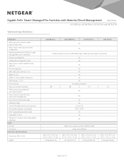
... yellow. The LED Mode button is not supplied to Ethernet Mode: Off. A valid 10 Mbps or 100 Mbps Ethernet link is established. 26-28 or ports 49-52 Solid green. Blinking yellow. Solid green. No SFP module link is established. Blinking green. Solid yellow. Power is set to PoE Mode: Off. PoE...
... yellow. The LED Mode button is not supplied to Ethernet Mode: Off. A valid 10 Mbps or 100 Mbps Ethernet link is established. 26-28 or ports 49-52 Solid green. Blinking yellow. Solid green. No SFP module link is established. Blinking green. Solid yellow. Power is set to PoE Mode: Off. PoE...
Hardware Installation Guide
Page 30
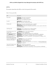
...into the connector. For model GS752TPv2 or model GS752TPP, use port 25, 26, 27, or 28. Press firmly on the switch. 2. Step 7: Connect devices to the switch The following procedure describes how to connect devices to seat it securely into the SFP port. To connect devices to an RJ-45 network... the flange of the module to the switch's RJ-45 ports. Connect a PoE or non-PoE device to the switch's RJ-45 ports: 1. For model GS728TPv2 or model GS728TPPv2, use port 49, 50, 51, or 52. 2. The switch supports Auto Uplink technology, which allows you to 328 feet (100 meters). ...
...into the connector. For model GS752TPv2 or model GS752TPP, use port 25, 26, 27, or 28. Press firmly on the switch. 2. Step 7: Connect devices to the switch The following procedure describes how to connect devices to seat it securely into the SFP port. To connect devices to an RJ-45 network... the flange of the module to the switch's RJ-45 ports. Connect a PoE or non-PoE device to the switch's RJ-45 ports: 1. For model GS728TPv2 or model GS728TPPv2, use port 49, 50, 51, or 52. 2. The switch supports Auto Uplink technology, which allows you to 328 feet (100 meters). ...

User Manual
Page 5
... Ethernet PoE+ Smart Managed Pro Switches with 4 SFP Ports Fan LED in the Device View 46 PoE Max LED in the Device View 46 LED Mode LED in the Device View 47 Configure interface settings 47 Access the NETGEAR support website 52 Access the user manual online 53 Chapter 2 Configure System Information View... 98 PoE concepts 98 Device class power requirements 98 Power allocation and power budget concepts 99 Configure the global PoE settings 101 Configure the PoE port settings 102 Configure SNMP 106 Configure the SNMPv1 and SNMPv2 community 106 5 User Manual
... Ethernet PoE+ Smart Managed Pro Switches with 4 SFP Ports Fan LED in the Device View 46 PoE Max LED in the Device View 46 LED Mode LED in the Device View 47 Configure interface settings 47 Access the NETGEAR support website 52 Access the user manual online 53 Chapter 2 Configure System Information View... 98 PoE concepts 98 Device class power requirements 98 Power allocation and power budget concepts 99 Configure the global PoE settings 101 Configure the PoE port settings 102 Configure SNMP 106 Configure the SNMPv1 and SNMPv2 community 106 5 User Manual
User Manual
Page 52
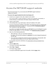
... displays. 6. Launch a web browser. 3. The Local Device Login page displays. If you did not yet register the switch with 4 SFP Ports Access the NETGEAR support website From the local browser UI, you can use a WiFi or wired connection to connect your computer to the network, or connect directly...default, the local device password is off -network on -network and connected to the same network as the switch. Get Started 52 User Manual To access the NETGEAR support site for the last Insight network location. Enter one of the following passwords: • After initial login, enter your ...
... displays. 6. Launch a web browser. 3. The Local Device Login page displays. If you did not yet register the switch with 4 SFP Ports Access the NETGEAR support website From the local browser UI, you can use a WiFi or wired connection to connect your computer to the network, or connect directly...default, the local device password is off -network on -network and connected to the same network as the switch. Get Started 52 User Manual To access the NETGEAR support site for the last Insight network location. Enter one of the following passwords: • After initial login, enter your ...

User Manual
Page 257
...reports. The number of received IGMP V2 reports. The number of received IGMP V1 reports. Configure Switching 257 User Manual Table 52. The number of transmitted IGMP leaves. For information about the switch, click the Refresh button. MVR Statistics information Field IGMP Query.... The following table describes the nonconfigurable information displayed on page 34. 5. The number of IGMP packet transmit failures. 24-Port and 48-Port Gigabit Ethernet PoE+ Smart Managed Pro Switches with the latest information about the credentials, see Credentials for the last Insight network...
...reports. The number of received IGMP V2 reports. The number of received IGMP V1 reports. Configure Switching 257 User Manual Table 52. The number of transmitted IGMP leaves. For information about the switch, click the Refresh button. MVR Statistics information Field IGMP Query.... The following table describes the nonconfigurable information displayed on page 34. 5. The number of IGMP packet transmit failures. 24-Port and 48-Port Gigabit Ethernet PoE+ Smart Managed Pro Switches with the latest information about the credentials, see Credentials for the last Insight network...

User Manual
Page 555
...) 011101 -> 1 (31) 011111 -> 1 (33) 100001 -> 2 (35) 100011 -> 2 (37) 100101 -> 2 (39) 100111 -> 2 (41) 101001 -> 2 (43) 101011 -> 2 (45) 101101 -> 2 (47) 101111 -> 2 (49) 110001 -> 3 (50) 110010 -> 3 (51) 110011 -> 3 (52) 110100 -> 3 (53) 110101 -> 3 (54) 110110 -> 3 (55) 110111 -> 3 (57) 111011 -> 3 (58) 111010 -> 3 (59) 111011 -> 3 (60) 111100 -> 3 (61) 111101 -> 3 (62) 111110 -> 3 (63) 111111 -> 3 802.1p 0 0 -> 1 1 -> 0 2 -> 0 3 -> 1 4 -> 2 5 -> 2 6 -> 3 7 -> 3 Specifications and...
...) 011101 -> 1 (31) 011111 -> 1 (33) 100001 -> 2 (35) 100011 -> 2 (37) 100101 -> 2 (39) 100111 -> 2 (41) 101001 -> 2 (43) 101011 -> 2 (45) 101101 -> 2 (47) 101111 -> 2 (49) 110001 -> 3 (50) 110010 -> 3 (51) 110011 -> 3 (52) 110100 -> 3 (53) 110101 -> 3 (54) 110110 -> 3 (55) 110111 -> 3 (57) 111011 -> 3 (58) 111010 -> 3 (59) 111011 -> 3 (60) 111100 -> 3 (61) 111101 -> 3 (62) 111110 -> 3 (63) 111111 -> 3 802.1p 0 0 -> 1 1 -> 0 2 -> 0 3 -> 1 4 -> 2 5 -> 2 6 -> 3 7 -> 3 Specifications and...


