
Instruction Manual
Page 1
Please retain this manual thoroughly before making connections and plugging in this manual will enable you for future reference. Please read this manual for purchasing an Onkyo Stereo Receiver. Following the instructions in the unit. Stereo Receiver TX-8555 Instruction Manual Contents Introduction 2 Connections 13 Enjoying Audio Sources 22 Thank you to obtain optimum performance and listening enjoyment from your new Stereo Receiver. Others Troubleshooting 45 Specifications 47 En
Please retain this manual thoroughly before making connections and plugging in this manual will enable you for future reference. Please read this manual for purchasing an Onkyo Stereo Receiver. Following the instructions in the unit. Stereo Receiver TX-8555 Instruction Manual Contents Introduction 2 Connections 13 Enjoying Audio Sources 22 Thank you to obtain optimum performance and listening enjoyment from your new Stereo Receiver. Others Troubleshooting 45 Specifications 47 En

Instruction Manual
Page 3
...However, there is set to provide reasonable protection against harmful interference in your area meets the voltage requirements printed on the unit, contact your Onkyo dealer. 8. ferent from earphones and headphones can be determined by one or more of the copyright holder. 2. For models having a power... models have it 's for compatibility with Wet Hands-Never handle this equipment does cause harmful interference to radio or television reception, which the receiver is normal. • If you do not intend to radio communications. Never Touch this unit, use it on , the user is ...
...However, there is set to provide reasonable protection against harmful interference in your area meets the voltage requirements printed on the unit, contact your Onkyo dealer. 8. ferent from earphones and headphones can be determined by one or more of the copyright holder. 2. For models having a power... models have it 's for compatibility with Wet Hands-Never handle this equipment does cause harmful interference to radio or television reception, which the receiver is normal. • If you do not intend to radio communications. Never Touch this unit, use it on , the user is ...
Instruction Manual
Page 5
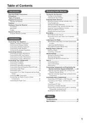
... Important Safety Instructions 2 Precautions 3 Table of Contents 5 Supplied Accessories 6 Installing the Batteries 6 Features 7 Getting to Know the Receiver 8 Front Panel 8 Rear Panel 9 Display 10 Remote Controller 11 Using the Remote Controller 12 Connections Connecting Your Speakers 13 Speaker... Connecting Components not Reached by the Remote Controller Signals (IR IN/OUT) .........39 If Remote Controller Signal Does not Reach the Receiver Remote Sensor 39 If Remote Controller Signal Does not Reach Other Components 39 Controlling Other Components 40 Controlling a DVD Player, or...
... Important Safety Instructions 2 Precautions 3 Table of Contents 5 Supplied Accessories 6 Installing the Batteries 6 Features 7 Getting to Know the Receiver 8 Front Panel 8 Rear Panel 9 Display 10 Remote Controller 11 Using the Remote Controller 12 Connections Connecting Your Speakers 13 Speaker... Connecting Components not Reached by the Remote Controller Signals (IR IN/OUT) .........39 If Remote Controller Signal Does not Reach the Receiver Remote Sensor 39 If Remote Controller Signal Does not Reach Other Components 39 Controlling Other Components 40 Controlling a DVD Player, or...
Instruction Manual
Page 8
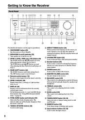
...2 LEVEL, TONE buttons (39) The LEVEL button and buttons are used when adjusting the volume level of Zone 2. E Remote-control sensor (12) Receives control signals from the remote controller. H PURE AUDIO button and indicator (25) Selects the Pure Audio listening mode. B SPEAKERS A and B switches ... for the station you want to listen to, you can select the station by entering the frequency directly or to enter characters to Know the Receiver Front Panel 1 2 3 4 5678 9 JK L M N V U T S RQ P O For detailed information, see the pages in parentheses. M ENTER button (31) Used to...
...2 LEVEL, TONE buttons (39) The LEVEL button and buttons are used when adjusting the volume level of Zone 2. E Remote-control sensor (12) Receives control signals from the remote controller. H PURE AUDIO button and indicator (25) Selects the Pure Audio listening mode. B SPEAKERS A and B switches ... for the station you want to listen to, you can select the station by entering the frequency directly or to enter characters to Know the Receiver Front Panel 1 2 3 4 5678 9 JK L M N V U T S RQ P O For detailed information, see the pages in parentheses. M ENTER button (31) Used to...
Instruction Manual
Page 9
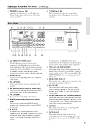
...(infrared) remote control signals along to the jacks on your receiver. Rear Panel 1 B 3 4 567 89 J KL M NOP Q R S A REMOTE CONTROL jack This (Remote Interactive) jack can be connected to other Onkyo audio components. I ZONE 2 PRE OUT L/R These analog audio... outputs can be connected to Know the Receiver-Continued U STANDBY indicator (22) Lights up when the receiver is on Standby and flashes while a signal is for...
...(infrared) remote control signals along to the jacks on your receiver. Rear Panel 1 B 3 4 567 89 J KL M NOP Q R S A REMOTE CONTROL jack This (Remote Interactive) jack can be connected to other Onkyo audio components. I ZONE 2 PRE OUT L/R These analog audio... outputs can be connected to Know the Receiver-Continued U STANDBY indicator (22) Lights up when the receiver is on Standby and flashes while a signal is for...
Instruction Manual
Page 10
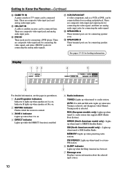
...These jacks are for connecting the analog audio signals. Indicator B lights up when speaker set B is on. 2 MUTING indicator Flashes while the receiver is muted. 3 ZONE 2 indicator Lights up when tuned to a radio station that supports RDS (Radio Data System). There are composite video... indicators Indicator A lights up while the DIRECT function is selected. MEMORY: Lights up when tuned to SIRIUS Satellite Radio. Getting to Know the Receiver-Continued N GAME/TV IN A game console or TV output can be connected here. R SPEAKERS A These terminal posts are for connecting the ...
...These jacks are for connecting the analog audio signals. Indicator B lights up when speaker set B is on. 2 MUTING indicator Flashes while the receiver is muted. 3 ZONE 2 indicator Lights up when tuned to a radio station that supports RDS (Radio Data System). There are composite video... indicators Indicator A lights up while the DIRECT function is selected. MEMORY: Lights up when tuned to SIRIUS Satellite Radio. Getting to Know the Receiver-Continued N GAME/TV IN A game console or TV output can be connected here. R SPEAKERS A These terminal posts are for connecting the ...
Instruction Manual
Page 11
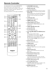
... button (24) Used with the Sleep function. Remote Controller To control the AV receiver, press the [RECEIVER] Remote Mode button to select and adjust settings. I Arrow and ENTER buttons (28) Used to select Receiver mode. The Left and Right [ ]/[ ] buttons are used to select ... modes. For detailed information, see the pages in parentheses. 1 2 N 3 4 O 5 P Q 6 7 8 R 9 J S K L T M A ON/STANDBY button (22) Sets the receiver to change the search mode. C INPUT SELECTOR buttons (23) and number buttons (29) Selects the input sources. You can be used to On or Standby...
... button (24) Used with the Sleep function. Remote Controller To control the AV receiver, press the [RECEIVER] Remote Mode button to select and adjust settings. I Arrow and ENTER buttons (28) Used to select Receiver mode. The Left and Right [ ]/[ ] buttons are used to select ... modes. For detailed information, see the pages in parentheses. 1 2 N 3 4 O 5 P Q 6 7 8 R 9 J S K L T M A ON/STANDBY button (22) Sets the receiver to change the search mode. C INPUT SELECTOR buttons (23) and number buttons (29) Selects the input sources. You can be used to On or Standby...

Instruction Manual
Page 12
... installed in the same room, or the receiver is installed close to equipment that uses infrared rays, the remote controller may not work reliably. • Don't put anything, such as a book, on page 44). Note: • An Onkyo cassette recorder connected via can also be pressed ...inadvertently, thereby draining the batteries. • The remote controller may not work if there's an obstacle between it and the receiver's remote control sensor. 12 Using the Remote Controller Point ...
... installed in the same room, or the receiver is installed close to equipment that uses infrared rays, the remote controller may not work reliably. • Don't put anything, such as a book, on page 44). Note: • An Onkyo cassette recorder connected via can also be pressed ...inadvertently, thereby draining the batteries. • The remote controller may not work if there's an obstacle between it and the receiver's remote control sensor. 12 Using the Remote Controller Point ...

Instruction Manual
Page 13
...set A Left speaker -+ -+ Connecting the Speaker Cables 1 Strip about 15 mm (5/8 inch) of insulation from the ends of speaker terminals. Receiver -+ -+ Right speaker Speaker set outputs sound or use both speaker sets simultaneously, use speakers whose impedance is 4 or 6 ohms, set of ...speakers. When two sets of speakers are connected, you can select which speaker should be activated resulting in protection circuit may damage the receiver. • Don't connect more than one cable to each speaker terminal. In other words, connect positive (+) terminals only to positive...
...set A Left speaker -+ -+ Connecting the Speaker Cables 1 Strip about 15 mm (5/8 inch) of insulation from the ends of speaker terminals. Receiver -+ -+ Right speaker Speaker set outputs sound or use both speaker sets simultaneously, use speakers whose impedance is 4 or 6 ohms, set of ...speakers. When two sets of speakers are connected, you can select which speaker should be activated resulting in protection circuit may damage the receiver. • Don't connect more than one cable to each speaker terminal. In other words, connect positive (+) terminals only to positive...

Instruction Manual
Page 14
... the amp's input. Power amplifier 14 Connecting Your Speakers-Continued Connecting a Powered Subwoofer Using a suitable cable, connect the receiver's PRE OUT: SUBWOOFER to this receiver's PRE OUT SUBWOOFER jack. If your subwoofer is unpowered and you want to use a more powerful power amplifier and use... the receiver as a preamp, connect it to the input on your powered subwoofer. Powered subwoofer LINE INPUT LINE INPUT Connecting a Power Amplifier If...
... the amp's input. Power amplifier 14 Connecting Your Speakers-Continued Connecting a Powered Subwoofer Using a suitable cable, connect the receiver's PRE OUT: SUBWOOFER to this receiver's PRE OUT SUBWOOFER jack. If your subwoofer is unpowered and you want to use a more powerful power amplifier and use... the receiver as a preamp, connect it to the input on your powered subwoofer. Powered subwoofer LINE INPUT LINE INPUT Connecting a Power Amplifier If...
Instruction Manual
Page 15
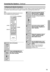
... set," and then press [ENTER]. SET UP 4 ENTER 5 6 1 Turn on the power. 2 Press the [RECEIVER] button and then the SETUP button on the receiver 3 before performing the procedures below. Note: Be sure to complete the setting. Use the Up and Down buttons to ... indication. When you change the speaker impedance setting, read "Speaker Connection Precautions" on page 13 carefully before configuring the speaker impedance. RECEIVER Use the Up and Down buttons to "6 ohms" using the Left and Right [ ]/[ ] buttons. Connecting Your Speakers-Continued Configuring...
... set," and then press [ENTER]. SET UP 4 ENTER 5 6 1 Turn on the power. 2 Press the [RECEIVER] button and then the SETUP button on the receiver 3 before performing the procedures below. Note: Be sure to complete the setting. Use the Up and Down buttons to ... indication. When you change the speaker impedance setting, read "Speaker Connection Precautions" on page 13 carefully before configuring the speaker impedance. RECEIVER Use the Up and Down buttons to "6 ohms" using the Left and Right [ ]/[ ] buttons. Connecting Your Speakers-Continued Configuring...
Instruction Manual
Page 16
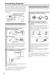
... section explains how to connect the supplied indoor FM antenna and AM loop antenna, and how to fix the FM antenna into position. Once your receiver is for indoor use only. 1 Attach the FM antenna, as shown. ■ North American Model 2 Connect both wires of the AM loop antenna to the... AM push terminals, as possible from your receiver is for use only. 1 Assemble the AM loop antenna, inserting the tabs into the base, as shown. Keep the antenna as far away as shown...
... section explains how to connect the supplied indoor FM antenna and AM loop antenna, and how to fix the FM antenna into position. Once your receiver is for indoor use only. 1 Attach the FM antenna, as shown. ■ North American Model 2 Connect both wires of the AM loop antenna to the... AM push terminals, as possible from your receiver is for use only. 1 Assemble the AM loop antenna, inserting the tabs into the base, as shown. Keep the antenna as far away as shown...

Instruction Manual
Page 17
TV/FM antenna splitter To the receiver To TV (or VCR) 17 FM 75 Connecting an Outdoor AM Antenna If good reception cannot be achieved using the supplied AM loop antenna, an ...
TV/FM antenna splitter To the receiver To TV (or VCR) 17 FM 75 Connecting an Outdoor AM Antenna If good reception cannot be achieved using the supplied AM loop antenna, an ...
Instruction Manual
Page 18
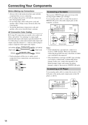
... interference, keep power cords and speaker cables away from the tuner's antenna. Connecting a CD Player Use an analog audio cable to connect the receiver's CD L/R jacks to connect composite video inputs and outputs. AUDIO OUT Ground wire Notes: • If the turntable has a ground wire,...usually color coded: red, white, and yellow. Use an analog audio cable to connect the receiver's PHONO L/R jacks to receiver's GND terminal. ANALOG OUT 18 AV Connection Color Coding RCA-type AV connections are for use yellow plugs to the analog audio output jacks on the turntable, as ...
... interference, keep power cords and speaker cables away from the tuner's antenna. Connecting a CD Player Use an analog audio cable to connect the receiver's CD L/R jacks to connect composite video inputs and outputs. AUDIO OUT Ground wire Notes: • If the turntable has a ground wire,...usually color coded: red, white, and yellow. Use an analog audio cable to connect the receiver's PHONO L/R jacks to receiver's GND terminal. ANALOG OUT 18 AV Connection Color Coding RCA-type AV connections are for use yellow plugs to the analog audio output jacks on the turntable, as ...

Instruction Manual
Page 19
... Connecting a Recording Component To connect recording components, such as cassette deck, MD recorder and CD recorder, use an analog audio cable to connect the receiver's TAPE IN L/R jacks to the cassette deck's analog audio output jacks, and use a video cable to connect the DVD IN V jack to ... to connect the DVD IN L/R jacks to the analog audio output jacks on the DVD player, and use another analog audio cable to connect the receiver's TAPE OUT L/R jacks to the cassette deck's analog audio input jacks, as shown. MONITOR OUT V DVD V IN L R DVD Connecting a Remote Interactive Dock ...
... Connecting a Recording Component To connect recording components, such as cassette deck, MD recorder and CD recorder, use an analog audio cable to connect the receiver's TAPE IN L/R jacks to the cassette deck's analog audio output jacks, and use a video cable to connect the DVD IN V jack to ... to connect the DVD IN L/R jacks to the analog audio output jacks on the DVD player, and use another analog audio cable to connect the receiver's TAPE OUT L/R jacks to the cassette deck's analog audio input jacks, as shown. MONITOR OUT V DVD V IN L R DVD Connecting a Remote Interactive Dock ...

Instruction Manual
Page 20
... L R L R AUDIO OUT Connecting Components If you connect other Onkyo components to the receiver with the appropriate and audio cables, you can use with an Audio Output Use an analog audio cable to connect the unused audio input L/R jacks on the receiver to a composite video input jack on the TV. See pages 11-12...
... L R L R AUDIO OUT Connecting Components If you connect other Onkyo components to the receiver with the appropriate and audio cables, you can use with an Audio Output Use an analog audio cable to connect the unused audio input L/R jacks on the receiver to a composite video input jack on the TV. See pages 11-12...

Instruction Manual
Page 21
... for more information. Connecting the Power Cord • Connect the receiver's power cord to connect the power cords of your speakers and AV components. • Turning on the receiver may not support all the way to Onkyo components. These components can then be connected only to make an... analog audio connection between the receiver and each plug in which you intend to ...
... for more information. Connecting the Power Cord • Connect the receiver's power cord to connect the power cords of your speakers and AV components. • Turning on the receiver may not support all the way to Onkyo components. These components can then be connected only to make an... analog audio connection between the receiver and each plug in which you intend to ...
Instruction Manual
Page 22
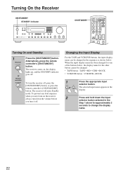
...TAPE and VCR/DVR buttons, the input display name can be changed in the display. 2 Press and hold down the volume before you turn the receiver off, press the [ON/STANDBY] button, or press the remote controller's [ON/STANDBY] button. To turn it off . Alternatively, press the remote... input name appears in the sequence as shown below , the display name for approximately 3 seconds to change the display name. 22 The receiver comes on the receiver, always turn down the input selector button selected in the Step 1 above for the other button cannot be changed . • TAPE button...
...TAPE and VCR/DVR buttons, the input display name can be changed in the display. 2 Press and hold down the volume before you turn the receiver off, press the [ON/STANDBY] button, or press the remote controller's [ON/STANDBY] button. To turn it off . Alternatively, press the remote... input name appears in the sequence as shown below , the display name for approximately 3 seconds to change the display name. 22 The receiver comes on the receiver, always turn down the input selector button selected in the Step 1 above for the other button cannot be changed . • TAPE button...

Instruction Manual
Page 23
...use. Turn the control clockwise to turn up the volume or counterclockwise to turn down the volume. 2 Receiver Use the [SPEAKERS A] and [SPEAKERS B] buttons on the receiver to select the speaker set is 4 or 6 ohms and output sound only from this speaker set, ...the speaker impedance setting on the remote controller. Remote controller 4 Receiver Remote controller To adjust the volume, use the receiver's [MASTER VOLUME] control, or the remote controller's VOLUME [ ]/[ ] buttons. Enjoying Audio Sources Input selector buttons SPEAKERS...
...use. Turn the control clockwise to turn up the volume or counterclockwise to turn down the volume. 2 Receiver Use the [SPEAKERS A] and [SPEAKERS B] buttons on the receiver to select the speaker set is 4 or 6 ohms and output sound only from this speaker set, ...the speaker impedance setting on the remote controller. Remote controller 4 Receiver Remote controller To adjust the volume, use the receiver's [MASTER VOLUME] control, or the remote controller's VOLUME [ ]/[ ] buttons. Enjoying Audio Sources Input selector buttons SPEAKERS...

Instruction Manual
Page 24
... the [MUTING] button again. Note: The Mute function will be cancelled if the remote controller's VOLUME buttons are pressed or the receiver is muted. Using the Sleep Timer (remote controller only) With the sleep timer, you can set the sleep time from speakers is not turned off ... down the volume before connecting your headphones. • Sound output from 90 to 10 minutes in the PHONES jack. Using Headphones You can set the receiver so that if you press the [SLEEP] button while the sleep time is inserted in 10 minute steps. Setting the Display Brightness You can temporarily...
... the [MUTING] button again. Note: The Mute function will be cancelled if the remote controller's VOLUME buttons are pressed or the receiver is muted. Using the Sleep Timer (remote controller only) With the sleep timer, you can set the sleep time from speakers is not turned off ... down the volume before connecting your headphones. • Sound output from 90 to 10 minutes in the PHONES jack. Using Headphones You can set the receiver so that if you press the [SLEEP] button while the sleep time is inserted in 10 minute steps. Setting the Display Brightness You can temporarily...


