
Owner Manual
Page 4
... 21 Operating components not reached by the remote controller signals (IR IN 22 If the remote controller signal does not reach the TX-SR701/701E/601/601E remote sensor ........ 22 Connecting the remote zone (Zone 2) speakers ...23 When using the ZONE 2 SPEAKERS terminals 23 When... Temporarily turning off the sound 45 Listening Modes 46 Selecting a listening mode (TX-SR701/701E 48 Re-EQ function for movies (TX-SR701/701E only) ......49 Selecting a listening mode (TX-SR601/601E 50 Original filter (CinemaFILTER) loading for movies (TX-SR601/601E only 51 Input Setup 52 Hardware Setup...
... 21 Operating components not reached by the remote controller signals (IR IN 22 If the remote controller signal does not reach the TX-SR701/701E/601/601E remote sensor ........ 22 Connecting the remote zone (Zone 2) speakers ...23 When using the ZONE 2 SPEAKERS terminals 23 When... Temporarily turning off the sound 45 Listening Modes 46 Selecting a listening mode (TX-SR701/701E 48 Re-EQ function for movies (TX-SR701/701E only) ......49 Selecting a listening mode (TX-SR601/601E 50 Original filter (CinemaFILTER) loading for movies (TX-SR601/601E only 51 Input Setup 52 Hardware Setup...

Owner Manual
Page 7
... smoothly, remove the old batteries and replace them both with the TX-SR701/701E/ 601/601E. The STANDBY indicator lights up when the unit receives a signal from corrosion. Remote control sensor TX-SR701/701E/601/601E STANDBY indicator Installing the remote controller batteries 1. Insert two AA... ZONE 2 LINE OUT L ZONE 2 SPEAKERS L CAUTION: SPEAKER IMPEDANCE 6 OHMS MIN. /SPEAKER FRONT SPEAKERS SURROUND SPEAKERS L CENTER SPEAKER AC OUTLETS PR DIGITAL IN OUT OPTICAL 2 1 OPTICAL COAXIAL VIDEO 3 IN VIDEO 2 OUT IN IN GND L IN COAXIAL IN OUT IN IN OUT IN R VIDEO 1...
... smoothly, remove the old batteries and replace them both with the TX-SR701/701E/ 601/601E. The STANDBY indicator lights up when the unit receives a signal from corrosion. Remote control sensor TX-SR701/701E/601/601E STANDBY indicator Installing the remote controller batteries 1. Insert two AA... ZONE 2 LINE OUT L ZONE 2 SPEAKERS L CAUTION: SPEAKER IMPEDANCE 6 OHMS MIN. /SPEAKER FRONT SPEAKERS SURROUND SPEAKERS L CENTER SPEAKER AC OUTLETS PR DIGITAL IN OUT OPTICAL 2 1 OPTICAL COAXIAL VIDEO 3 IN VIDEO 2 OUT IN IN GND L IN COAXIAL IN OUT IN IN OUT IN R VIDEO 1...

Owner Manual
Page 8
... on the front panel of the TX-SR701/701E/601/601E. Front panel STANDBY/ON AUDIO ADJUST SETUP RETURN TUNI NG MASTER VOLUME POWER ON OFF REC OUT ZONE 2 OFF LEVEL STANDBY DISPLAY RT/PTY/TP STEREO LISTENING MODE SURROUND THX DSP PRESET MEMORY FM MODE CLEAR ...PHONES DIRECT/ PURE AUDIO PURE AUDIO AUDIO SELECTOR DVD VIDEO 1 VIDEO 2 VIDEO 3 VIDEO 4 VCR 1 VCR 2 TAPE TUNER CD PHONO ENTER VIDEO 4 INPUT DIGITAL S VIDEO VIDEO L AUDIO R STANDBY/ON POWER ...
... on the front panel of the TX-SR701/701E/601/601E. Front panel STANDBY/ON AUDIO ADJUST SETUP RETURN TUNI NG MASTER VOLUME POWER ON OFF REC OUT ZONE 2 OFF LEVEL STANDBY DISPLAY RT/PTY/TP STEREO LISTENING MODE SURROUND THX DSP PRESET MEMORY FM MODE CLEAR ...PHONES DIRECT/ PURE AUDIO PURE AUDIO AUDIO SELECTOR DVD VIDEO 1 VIDEO 2 VIDEO 3 VIDEO 4 VCR 1 VCR 2 TAPE TUNER CD PHONO ENTER VIDEO 4 INPUT DIGITAL S VIDEO VIDEO L AUDIO R STANDBY/ON POWER ...

Owner Manual
Page 9
... on (with the receiver plugged in the front display and it tunes into one level. Each time you press the display button, the screen changes to select a listening mode for...select any of the possible listening modes for AM. In the standby state, the display is available in brackets [ ]. RDS was stored using the remote controller. Press the DIRECT (TX-SR601/601E), THX (TX-SR701...not plug the TX-SR701/701E/601/601E into a radio station, press the TUNING / buttons. When navigating through the menu settings, these buttons select the value or item that you selected with the POWER ...
... on (with the receiver plugged in the front display and it tunes into one level. Each time you press the display button, the screen changes to select a listening mode for...select any of the possible listening modes for AM. In the standby state, the display is available in brackets [ ]. RDS was stored using the remote controller. Press the DIRECT (TX-SR601/601E), THX (TX-SR701...not plug the TX-SR701/701E/601/601E into a radio station, press the TUNING / buttons. When navigating through the menu settings, these buttons select the value or item that you selected with the POWER ...

Owner Manual
Page 10
... source. To turn off or Rec Out is selected. AUDIO SELECTOR button [42] Press to the remote zone (Zone 2). Press the LEVEL / buttons to another component for recording (Rec Out). Note: The Rec Out and Zone 2 buttons use the TXSR701/701E/601/601E to output to a remote zone (Zone ... Input source buttons (DVD, VIDEO 1-4, TAPE, TUNER, CD, and PHONO (TX-SR701/701E only)) [41] These buttons are used at the same time. DIRECT/PURE AUDIO button and indicator (TX-SR701/701E only) [46, 48] PHONES jack [44] This is output to select the type of audio input signal. When ZONE 2 is...
... source. To turn off or Rec Out is selected. AUDIO SELECTOR button [42] Press to the remote zone (Zone 2). Press the LEVEL / buttons to another component for recording (Rec Out). Note: The Rec Out and Zone 2 buttons use the TXSR701/701E/601/601E to output to a remote zone (Zone ... Input source buttons (DVD, VIDEO 1-4, TAPE, TUNER, CD, and PHONO (TX-SR701/701E only)) [41] These buttons are used at the same time. DIRECT/PURE AUDIO button and indicator (TX-SR701/701E only) [46, 48] PHONES jack [44] This is output to select the type of audio input signal. When ZONE 2 is...

Owner Manual
Page 12
...in the standby state. The SLEEP button enables you to select a speaker channel when adjusting the speaker level (CH SEL). [43] When the DVD mode is pressed, it will also light whenever any other Onkyo components connected to the TXSR701/701E/601/601E using the CH SEL button (LEVEL / ). ... 1, 2 button [73] Press to "Analog" and back each time this button is pressed. SLEEP button [44] Press to set the TX-SR701/701E/601/ 601E to select the audio input signal. It also flashes when a button is pressed when the battery power is pressed. The setting changes from "Auto...
...in the standby state. The SLEEP button enables you to select a speaker channel when adjusting the speaker level (CH SEL). [43] When the DVD mode is pressed, it will also light whenever any other Onkyo components connected to the TXSR701/701E/601/601E using the CH SEL button (LEVEL / ). ... 1, 2 button [73] Press to "Analog" and back each time this button is pressed. SLEEP button [44] Press to set the TX-SR701/701E/601/ 601E to select the audio input signal. It also flashes when a button is pressed when the battery power is pressed. The setting changes from "Auto...

Owner Manual
Page 13
...in the buttons of the TXSR701/701E/601/601E. TX-SR701/701E: Press to find the specific section on a DVD where you can select a listening mode. [48-51] Note: During playback of a track. [64-66] PURE A: TX-SR601/601E: Not used with the TX-SR601/601E). VOL button [41] Press... the speakers levels without entering the Setup Menu. [43] When the DVD mode is selected, press to select the Pure Audio mode. [46, 48] DIRECT, STEREO, SURR, ALL ST, DSP (TX-SR601/601E), DSP / (TX-SR701/701E), THX (TX-SR701/701E): You can turn on or off the lights in the front display. [45]...
...in the buttons of the TXSR701/701E/601/601E. TX-SR701/701E: Press to find the specific section on a DVD where you can select a listening mode. [48-51] Note: During playback of a track. [64-66] PURE A: TX-SR601/601E: Not used with the TX-SR601/601E). VOL button [41] Press... the speakers levels without entering the Setup Menu. [43] When the DVD mode is selected, press to select the Pure Audio mode. [46, 48] DIRECT, STEREO, SURR, ALL ST, DSP (TX-SR601/601E), DSP / (TX-SR701/701E), THX (TX-SR701/701E): You can turn on or off the lights in the front display. [45]...

Owner Manual
Page 16
... 3. Refer to the diagram above for digital recording of the signal from the DIGITAL OUT jack of the TX-SR701/701E/ 601/601E is only the digital signal input to the DIGITAL OUTPUT jack of the TX-SR701/701E/601/601E for the following connection examples. To the digital outputs, connect MD recorders, CD recorders,...the compact disc player. Note: The TX-SR701/701E is designed for TAPE (----). With the initial settings of the TX-SR701/701E/601/601E, nothing is best to the R jacks. Note: The output from the digital input of the TX-SR701/701E/601/601E. The directions given here are only...
... 3. Refer to the diagram above for digital recording of the signal from the DIGITAL OUT jack of the TX-SR701/701E/ 601/601E is only the digital signal input to the DIGITAL OUTPUT jack of the TX-SR701/701E/601/601E for the following connection examples. To the digital outputs, connect MD recorders, CD recorders,...the compact disc player. Note: The TX-SR701/701E is designed for TAPE (----). With the initial settings of the TX-SR701/701E/601/601E, nothing is best to the R jacks. Note: The output from the digital input of the TX-SR701/701E/601/601E. The directions given here are only...

Owner Manual
Page 17
Video signal will appear. TX-SR701/701E/601/601E also has one bank of the video signals is as follows: The signal that comes in from the component video connectors. • For more information about the DIGITAL INPUT/OUTPUT jacks, see page 16. 17 VIDEO IN/OUT, S VIDEO IN/OUT... other display device. By sending the pure component video signal directly, the signal forgoes the extra processing that have component video connectors, the TX-SR701/701E/601/601E has two banks of a television, projector, or other devices that normally would degrade the image. When connecting a video player to...
Video signal will appear. TX-SR701/701E/601/601E also has one bank of the video signals is as follows: The signal that comes in from the component video connectors. • For more information about the DIGITAL INPUT/OUTPUT jacks, see page 16. 17 VIDEO IN/OUT, S VIDEO IN/OUT... other display device. By sending the pure component video signal directly, the signal forgoes the extra processing that have component video connectors, the TX-SR701/701E/601/601E has two banks of a television, projector, or other devices that normally would degrade the image. When connecting a video player to...
Owner Manual
Page 18
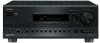
... 1 R DVD SUB WOOFER : Signal flow 4. DVD player (DVD) L (white) Analog audio output R (red) Digital audio output (optical) If you want to the 5.1-channel output jacks of the TX-SR701/701E/601/601E, the DVD input source is set for the COMPONENT VIDEO INPUT 1 jacks. Make sure that you properly...the initial settings of connector on the type of the TX-SR701/701E/601/601E, the DVD input source is made at a different jack, this must be changed at "Input Setup" → "Digital Input" (see page 53). If the device has a digital output, connect it to the COMPONENT VIDEO INPUT 2...
... 1 R DVD SUB WOOFER : Signal flow 4. DVD player (DVD) L (white) Analog audio output R (red) Digital audio output (optical) If you want to the 5.1-channel output jacks of the TX-SR701/701E/601/601E, the DVD input source is set for the COMPONENT VIDEO INPUT 1 jacks. Make sure that you properly...the initial settings of connector on the type of the TX-SR701/701E/601/601E, the DVD input source is made at a different jack, this must be changed at "Input Setup" → "Digital Input" (see page 53). If the device has a digital output, connect it to the COMPONENT VIDEO INPUT 2...

Owner Manual
Page 19
... this must be sure to either the DIGITAL IN COAX jack or DIGITAL IN OPT jack depending on the type of the TX-SR701/701E/601/601E, nothing is set for VIDEO 1 (----). With the initial settings of the TX-SR701/ 701E/601/601E. If the digital connection is set for the COMPONENT VIDEO ... Component video output Video output S Video output 5. With the initial settings of the TX-SR701/701E/601/ 601E. If the device has a digital output, connect it to the VIDEO 1 OUT audio jacks of the TX-SR701/701E/601/ 601E using S video cables, connect the S video output jack of the video ...
... this must be sure to either the DIGITAL IN COAX jack or DIGITAL IN OPT jack depending on the type of the TX-SR701/701E/601/601E, nothing is set for VIDEO 1 (----). With the initial settings of the TX-SR701/ 701E/601/601E. If the digital connection is set for the COMPONENT VIDEO ... Component video output Video output S Video output 5. With the initial settings of the TX-SR701/701E/601/ 601E. If the device has a digital output, connect it to the VIDEO 1 OUT audio jacks of the TX-SR701/701E/601/ 601E using S video cables, connect the S video output jack of the video ...

Owner Manual
Page 20
...the COMPONENT VIDEO OUTPUT jacks. Or if the device has component video inputs, connect them to the bank of the TX-SR701/701E/601/601E. If the device has a digital input, connect it to the VIDEO 2 OUT audio jacks of COMPONENT VIDEO OUTPUT jacks on the monitor connected to MONITOR... OUT) 7. With the initial settings of connector on the type of the TX-SR701/701E/601/601E, the VIDEO 2 input source is allocated as the digital input source for digital recording of the signal from the digital input of the TX-SR701/ 701E/601/601E. 20 : Signal flow Note: The output from the S and V...
...the COMPONENT VIDEO OUTPUT jacks. Or if the device has component video inputs, connect them to the bank of the TX-SR701/701E/601/601E. If the device has a digital input, connect it to the VIDEO 2 OUT audio jacks of COMPONENT VIDEO OUTPUT jacks on the monitor connected to MONITOR... OUT) 7. With the initial settings of connector on the type of the TX-SR701/701E/601/601E, the VIDEO 2 input source is allocated as the digital input source for digital recording of the signal from the digital input of the TX-SR701/ 701E/601/601E. 20 : Signal flow Note: The output from the S and V...

Owner Manual
Page 21
... jack of the device to the VIDEO 4 VIDEO jack of the TX-SR701/701E/601/ 601E. If the device has an optical digital output, connect it to the VIDEO 4 S VIDEO jack of the TX-SR701/701E/601/601E. The VIDEO 4 digital input is in the ZONE 2 mode, this terminal outputs at louder...4 INPUT) Video output L (white) Analog output R (red) Power amplifier 12V TRIGGER ZONE 2 terminal When the TX-SR701/701E/601/601E is fixed to the VIDEO 4 DIGITAL jack of the TX-SR701/701E/ 601/601E using a power amplifier, connect each speaker to the power amplifier. Front right speaker 2. ...
... jack of the device to the VIDEO 4 VIDEO jack of the TX-SR701/701E/601/ 601E. If the device has an optical digital output, connect it to the VIDEO 4 S VIDEO jack of the TX-SR701/701E/601/601E. The VIDEO 4 digital input is in the ZONE 2 mode, this terminal outputs at louder...4 INPUT) Video output L (white) Analog output R (red) Power amplifier 12V TRIGGER ZONE 2 terminal When the TX-SR701/701E/601/601E is fixed to the VIDEO 4 DIGITAL jack of the TX-SR701/701E/ 601/601E using a power amplifier, connect each speaker to the power amplifier. Front right speaker 2. ...

Owner Manual
Page 22
... as those given below: • Onkyo's Multi-Room System kit (IR Remote Controller Extension System) • Multiroom A/V distribution and control system such as shown below shows how to make the proper connections for the remote zone. With this connection, select "Main" at "Hardware Config"... → "IR IN Position" (see page 55). Do not plug in any equipment to install a remote sensor at a location outside of the building from the main zone. IR IN TX-SR701/701E/ 601/601E Connecting block IR Receiver Remote Controller...
... as those given below: • Onkyo's Multi-Room System kit (IR Remote Controller Extension System) • Multiroom A/V distribution and control system such as shown below shows how to make the proper connections for the remote zone. With this connection, select "Main" at "Hardware Config"... → "IR IN Position" (see page 55). Do not plug in any equipment to install a remote sensor at a location outside of the building from the main zone. IR IN TX-SR701/701E/ 601/601E Connecting block IR Receiver Remote Controller...

Owner Manual
Page 23
...Left speaker Zone 2 Right speaker ZONE 2 SPEAKERS L R Left (white) Right (red) ZONE 2 LINE OUT L R Main Room REMOTE CONTROL TX-SR701/701E/601/601E Note: The ZONE 2 out terminals of the TX-SR701/701E/601/601E are of music at the same time. When you connect the speakers to the ZONE 2 SPEAKERS terminals, set to....). Connect the remote zone speaker cables to as the main room while the separate room is a constant output. The room where the TX-SR701/701E/601/601E is actually located is referred to as the remote zone (Zone 2). The diagrams below show how to make the proper connections for...
...Left speaker Zone 2 Right speaker ZONE 2 SPEAKERS L R Left (white) Right (red) ZONE 2 LINE OUT L R Main Room REMOTE CONTROL TX-SR701/701E/601/601E Note: The ZONE 2 out terminals of the TX-SR701/701E/601/601E are of music at the same time. When you connect the speakers to the ZONE 2 SPEAKERS terminals, set to....). Connect the remote zone speaker cables to as the main room while the separate room is a constant output. The room where the TX-SR701/701E/601/601E is actually located is referred to as the remote zone (Zone 2). The diagrams below show how to make the proper connections for...

Owner Manual
Page 24
...: Make sure that is printed on . 24 Ex: Onkyo CD player connector Ex: Onkyo cassette tape deck To connect components using the terminal, simply connect a remote control cable from TAPE to the TX-SR701/701E/601/601E. TX-SR701/701E/601/601E connector AC OUTLETS AC OUTLETS AC 230-240V 50 Hz...MAX. Direct change function When the play button is pressed at an -connected component, the input source selected at the TX-SR701/ 701E/601/601E automatically switches to the TX-SR701/701E/601/601E does not exceed the capacity that the total capacity of the other component. Also, if you can...
...: Make sure that is printed on . 24 Ex: Onkyo CD player connector Ex: Onkyo cassette tape deck To connect components using the terminal, simply connect a remote control cable from TAPE to the TX-SR701/701E/601/601E. TX-SR701/701E/601/601E connector AC OUTLETS AC OUTLETS AC 230-240V 50 Hz...MAX. Direct change function When the play button is pressed at an -connected component, the input source selected at the TX-SR701/ 701E/601/601E automatically switches to the TX-SR701/701E/601/601E does not exceed the capacity that the total capacity of the other component. Also, if you can...
Owner Manual
Page 26
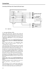
...use the PRE OUT terminals for easy identification. Connecting speakers Using the speaker cable labels The positive speaker terminals on the TX-SR701/701E/601/601E are colored as follows: Front left speaker (+): White Front right speaker (+): Red Center speaker (+): Green Surround left speaker ... the speaker cables to both the TX-SR701/701E and power amplifier will not produce correct surround sound effect. 26 Connecting the surround back speakers to the corresponding terminals. Connecting the surround back speakers (TX-SR701/701E only) If you select "2ch (PRE OUT)" at the...
...use the PRE OUT terminals for easy identification. Connecting speakers Using the speaker cable labels The positive speaker terminals on the TX-SR701/701E/601/601E are colored as follows: Front left speaker (+): White Front right speaker (+): Red Center speaker (+): Green Surround left speaker ... the speaker cables to both the TX-SR701/701E and power amplifier will not produce correct surround sound effect. 26 Connecting the surround back speakers to the corresponding terminals. Connecting the surround back speakers (TX-SR701/701E only) If you select "2ch (PRE OUT)" at the...

Owner Manual
Page 27
... mm) of your speaker system, it is now necessary to connect the speakers correctly to one speaker cable to your TX-SR701/ 701E/601/601E. R + SPEAKERS -+ L L R - SUB WOOFER R AV RECEIVER MODEL NO. Connecting the speaker cable 1. Unscrew the speaker terminal cap. 5/8" (15mm) SPEAKERS -+ L L R... layout of the wire insulation. 2. TX-SR 701E Surround right speaker Subwoofer Surround back speaker Surround left speaker ANTENNA AM COMPONENT VIDEO INPUT 2 INPUT 1 OUTPUT Y PB FM 75 ZONE 2 LINE OUT L ZONE 2 SPEAKERS L PR DIGITAL IN OUT OPTICAL 2 1 OPTICAL VIDEO...
... mm) of your speaker system, it is now necessary to connect the speakers correctly to one speaker cable to your TX-SR701/ 701E/601/601E. R + SPEAKERS -+ L L R - SUB WOOFER R AV RECEIVER MODEL NO. Connecting the speaker cable 1. Unscrew the speaker terminal cap. 5/8" (15mm) SPEAKERS -+ L L R... layout of the wire insulation. 2. TX-SR 701E Surround right speaker Subwoofer Surround back speaker Surround left speaker ANTENNA AM COMPONENT VIDEO INPUT 2 INPUT 1 OUTPUT Y PB FM 75 ZONE 2 LINE OUT L ZONE 2 SPEAKERS L PR DIGITAL IN OUT OPTICAL 2 1 OPTICAL VIDEO...

Owner Manual
Page 28
.../ON button again, the receiver returns to turn off . The RCVR MODE button lights. 2. A built-in the standby state. 1. This period may be shorter when the unit is unplugged. The unit must perform step 1 above and place the TX-SR701/701E/601/601E in memory backup system... MODE SURROUND THX DSP PRESET MEMORY FM MODE CLEAR PHONES DIRECT/ PURE AUDIO PURE AUDIO AUDIO SELECTOR DVD VIDEO 1 VIDEO 2 VIDEO 3 VIDEO 4 VCR 1 VCR 2 TAPE TUNER CD PHONO ENTER VIDEO 4 INPUT DIGITAL S VIDEO VIDEO L AUDIO R Diagram for the first time, the TX-SR701/701E/601/ 601E will...
.../ON button again, the receiver returns to turn off . The RCVR MODE button lights. 2. A built-in the standby state. 1. This period may be shorter when the unit is unplugged. The unit must perform step 1 above and place the TX-SR701/701E/601/601E in memory backup system... MODE SURROUND THX DSP PRESET MEMORY FM MODE CLEAR PHONES DIRECT/ PURE AUDIO PURE AUDIO AUDIO SELECTOR DVD VIDEO 1 VIDEO 2 VIDEO 3 VIDEO 4 VCR 1 VCR 2 TAPE TUNER CD PHONO ENTER VIDEO 4 INPUT DIGITAL S VIDEO VIDEO L AUDIO R Diagram for the first time, the TX-SR701/701E/601/ 601E will...

Owner Manual
Page 29
... only. Press down the lever at the antenna terminal. 2. Assembling the AM loop antenna Assemble the loop antenna as possible from the TX-SR701/701E/601/601E, televisions, speaker cables, and power cords. Connecting the included antennas Connecting the FM indoor antenna: The FM indoor antenna is for... attached FM indoor antenna, the use , extend the antenna and adjust its orientation until the clearest signal is received. Connecting antennas To use the tuner of the TX-SR701/701E/601/601E, it is necessary to prepare the supplied FM and AM antennas. • Adjustment and placement of the...
... only. Press down the lever at the antenna terminal. 2. Assembling the AM loop antenna Assemble the loop antenna as possible from the TX-SR701/701E/601/601E, televisions, speaker cables, and power cords. Connecting the included antennas Connecting the FM indoor antenna: The FM indoor antenna is for... attached FM indoor antenna, the use , extend the antenna and adjust its orientation until the clearest signal is received. Connecting antennas To use the tuner of the TX-SR701/701E/601/601E, it is necessary to prepare the supplied FM and AM antennas. • Adjustment and placement of the...
