

Owner Manual
Page 1
... antenna connections 12 Connecting Onkyo components for R I operation 14 Basic operations 15 Receiving stations 18 Using preset stations 19 Use of surround mode 20 Parameter selector 20 Setting the surround parameters 21 Karaoke function (TX-SE500 only)...,,.... 24 Recording a source 25 Troubleshooting guide 27 Specifications 28 ON KILTO TX-SV444 Audio Video Control Receiver...
... antenna connections 12 Connecting Onkyo components for R I operation 14 Basic operations 15 Receiving stations 18 Using preset stations 19 Use of surround mode 20 Parameter selector 20 Setting the surround parameters 21 Karaoke function (TX-SE500 only)...,,.... 24 Recording a source 25 Troubleshooting guide 27 Specifications 28 ON KILTO TX-SV444 Audio Video Control Receiver...
Owner Manual
Page 2
...8226; For models having a power cord with 2 mic inputs, voice cancel, pitch, echo and separate volume controls (TX-SE500) • Dolby- Please retain this manual will not occur in accordance with the following measures: • Reorient or relocate the receiving antenna. • Increase the... lead are coloured in a particular installation. However, there is no guarantee that the ONKYO product described in the mains lead of Dolby Laboratories Licensing Corporation. If this manual thoroughly before making connections and turning on whole system with the limits for enhanced low ...
...8226; For models having a power cord with 2 mic inputs, voice cancel, pitch, echo and separate volume controls (TX-SE500) • Dolby- Please retain this manual will not occur in accordance with the following measures: • Reorient or relocate the receiving antenna. • Increase the... lead are coloured in a particular installation. However, there is no guarantee that the ONKYO product described in the mains lead of Dolby Laboratories Licensing Corporation. If this manual thoroughly before making connections and turning on whole system with the limits for enhanced low ...

Owner Manual
Page 7
Audio equipment connections • On each pair of input jacks, the lower jack (marked R, red) corresponds to the right channel, and the upper jack (marked L, white) to the left channel. • Please refer to the instruction manual of each component when making any connections. • This receiver is designed for use with turntables using moving magnet cartridges. Turntable 0 PHONO OUT U MULTI. PUT SL, .{I D e CENTER SPEAKER rri See gt; 1
Audio equipment connections • On each pair of input jacks, the lower jack (marked R, red) corresponds to the right channel, and the upper jack (marked L, white) to the left channel. • Please refer to the instruction manual of each component when making any connections. • This receiver is designed for use with turntables using moving magnet cartridges. Turntable 0 PHONO OUT U MULTI. PUT SL, .{I D e CENTER SPEAKER rri See gt; 1
Owner Manual
Page 8
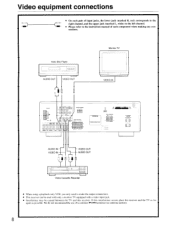
R - - VIDEO IN rVIDEO OUT AUDIO OUT 0 Video Cassette Recorder • When using a playback-only VCR, you only need to the instruction manual of a common TV/FM antenna (see antenna section). 8 T t DODO El EICIEI 0 oarmra COM REAR SPEAKERS CD AUDIO IN - We do not recommend the use of ...
R - - VIDEO IN rVIDEO OUT AUDIO OUT 0 Video Cassette Recorder • When using a playback-only VCR, you only need to the instruction manual of a common TV/FM antenna (see antenna section). 8 T t DODO El EICIEI 0 oarmra COM REAR SPEAKERS CD AUDIO IN - We do not recommend the use of ...

Owner Manual
Page 18
... is received, scanning stops. UP „ the frequency increases. When a broadcast is flashing. Receiving stations D RECT TUNING -4 DOWN TUNING UP P. 1-9, 0/10 FM AM 2 . Receiving RDS (TX-SV444 European model only) When an RDS (Radio Data System) station broadcasting PS (Program Service Name) information is received, the RDS indicator lights up and name.... Select a station you tune in areas where RDS broadcasts are scanned automatically (FM auto tuning mode). If the signal is held continuously for the I MHz Manual tuning 1. Use the TUNING UP/DOWN buttons to .
... is received, scanning stops. UP „ the frequency increases. When a broadcast is flashing. Receiving stations D RECT TUNING -4 DOWN TUNING UP P. 1-9, 0/10 FM AM 2 . Receiving RDS (TX-SV444 European model only) When an RDS (Radio Data System) station broadcasting PS (Program Service Name) information is received, the RDS indicator lights up and name.... Select a station you tune in areas where RDS broadcasts are scanned automatically (FM auto tuning mode). If the signal is held continuously for the I MHz Manual tuning 1. Use the TUNING UP/DOWN buttons to .
Owner Manual
Page 25
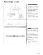
diagram (page 7). 1. Press the input selector button for the source you want to the tape deck instruction manual for recording. • Please read the instruction manuals concerning the operation of each unit. indicator is not lit on the display. To stop monitoring, press the TAPE button again while holding down the ...
diagram (page 7). 1. Press the input selector button for the source you want to the tape deck instruction manual for recording. • Please read the instruction manuals concerning the operation of each unit. indicator is not lit on the display. To stop monitoring, press the TAPE button again while holding down the ...

Owner Manual
Page 26
... recorded onto a VCR (VIDEO-2). 1. Insert the disc or tape that is connected to the VIDEO-2 terminal. Press the VIDEO-1/VDP button. 4. DVD or VCR instruction manuals for additional information. 3 VIDEO-NV, 4 NAM% TAPP,MONITORI FM AM PHONO CC 26 Select the audio program source (TV/ AUX, TAPE, FM, AM, PHONO, CD...
... recorded onto a VCR (VIDEO-2). 1. Insert the disc or tape that is connected to the VIDEO-2 terminal. Press the VIDEO-1/VDP button. 4. DVD or VCR instruction manuals for additional information. 3 VIDEO-NV, 4 NAM% TAPP,MONITORI FM AM PHONO CC 26 Select the audio program source (TV/ AUX, TAPE, FM, AM, PHONO, CD...
Owner Manual
Page 27
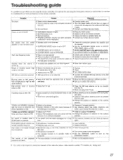
...., being used. 27 KARAOKE indicator. source is not heard. • Set it to the playback source. • Also refer to the respective instruction manuals of the cable to reduce hum. Hum, low-frequency noise. • Poor or no input ground. • Poor or no sound. • ...antenna. Buzzing noise on AM, FM. • Noise caused by the remote controller. • Check connections, speaker leads, etc. • Contact your Onkyo Service Center. larly conspicuous at night or with cent lamp. • Set up . • Move them farther apart. weak stations). Crackling noise on...
...., being used. 27 KARAOKE indicator. source is not heard. • Set it to the playback source. • Also refer to the respective instruction manuals of the cable to reduce hum. Hum, low-frequency noise. • Poor or no input ground. • Poor or no sound. • ...antenna. Buzzing noise on AM, FM. • Noise caused by the remote controller. • Check connections, speaker leads, etc. • Contact your Onkyo Service Center. larly conspicuous at night or with cent lamp. • Set up . • Move them farther apart. weak stations). Crackling noise on...

