

AGMX70 User Guide
Page 2
...harmful interference in a commercial environment. WARNING: TO REDUCE THE RISK OF FIRE OR SHOCK HAZARD, KEEP THIS EQUIPMENT AWAY FROM ALL LIQUIDS-USE AND STORE ONLY IN LOCATIONS WHICH ARE NOT EXPOSED TO THE RISK OF DRIPPING OR SPLASHING LIQUIDS, AND DO NOT PLACE ANY LIQUID ...CONTAINERS ON TOP OF THE EQUIPMENT. CAUTION: TO REDUCE THE RISK OF FIRE OR SHOCK HAZARD AND ANNOYING INTERFERENCE, USE THE RECOMMENDED ACCESSORIES ONLY. To assure continued compliance follow the attached installation instructions and do not obstruct the ventilation to prevent risk of electric...
...harmful interference in a commercial environment. WARNING: TO REDUCE THE RISK OF FIRE OR SHOCK HAZARD, KEEP THIS EQUIPMENT AWAY FROM ALL LIQUIDS-USE AND STORE ONLY IN LOCATIONS WHICH ARE NOT EXPOSED TO THE RISK OF DRIPPING OR SPLASHING LIQUIDS, AND DO NOT PLACE ANY LIQUID ...CONTAINERS ON TOP OF THE EQUIPMENT. CAUTION: TO REDUCE THE RISK OF FIRE OR SHOCK HAZARD AND ANNOYING INTERFERENCE, USE THE RECOMMENDED ACCESSORIES ONLY. To assure continued compliance follow the attached installation instructions and do not obstruct the ventilation to prevent risk of electric...
AGMX70 User Guide
Page 3
Since its downstream keys, fade controls and audio mixers can also be used, the effects required for AB roll editing can also be provided by adding the 3D optional board (AG-VE70). ≥ Audio mixing The unit comes ... unit is equipped with GPI and RS-422A/RS-232C connectors to enable an external editing controller to be connected. ≥ Digital effect functions By using the unit's internal digital memory, it unnecessary for two video signals to the wipe, mix and digital effects, this one unit. Ripple, multi, spark and...
Since its downstream keys, fade controls and audio mixers can also be used, the effects required for AB roll editing can also be provided by adding the 3D optional board (AG-VE70). ≥ Audio mixing The unit comes ... unit is equipped with GPI and RS-422A/RS-232C connectors to enable an external editing controller to be connected. ≥ Digital effect functions By using the unit's internal digital memory, it unnecessary for two video signals to the wipe, mix and digital effects, this one unit. Ripple, multi, spark and...
AGMX70 User Guide
Page 5
... 75 By data type 75 Display methods 75 DSK effects 75 Image size 75 Image formats supported 75 Management of the image memory 76 Before use 77 AG-MX70 connections 77 Installation of the USB driver 77 For Windows 98 and Windows 2000 77 For Windows ME 78 For Windows XP...
... 75 By data type 75 Display methods 75 DSK effects 75 Image size 75 Image formats supported 75 Management of the image memory 76 Before use 77 AG-MX70 connections 77 Installation of the USB driver 77 For Windows 98 and Windows 2000 77 For Windows ME 78 For Windows XP...
AGMX70 User Guide
Page 6
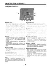
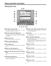
... panel settings are stored in the memory. 5 CENTER button Centering is performed when this button is set to OFF. 2 Joystick The joystick is used . Updating to the joystick value occurs when this button is set to ON. It can be exited by selecting [Enter]. It is possible to...demo mode is established after the power is switched as required. Select "Power" from the editor are canceled. 7 ASPECT ratio control This control is used to set the aspect ratio for the color settings. In the case of position settings, the pattern is centered. 6 HOLD button The joystick operation...
... panel settings are stored in the memory. 5 CENTER button Centering is performed when this button is set to OFF. 2 Joystick The joystick is used . Updating to the joystick value occurs when this button is set to ON. It can be exited by selecting [Enter]. It is possible to...demo mode is established after the power is switched as required. Select "Power" from the editor are canceled. 7 ASPECT ratio control This control is used to set the aspect ratio for the color settings. In the case of position settings, the pattern is centered. 6 HOLD button The joystick operation...

AGMX70 User Guide
Page 7
... setting, and some patterns cannot be selected. If DSK-Effects has been set to the ON position, the transition pattern and 3D-DVE are used to a pattern from one direction. The button's lamp flashes with preset bus or program bus or with patterns that have no reverse operations, ... is stored in the memory. 3 DSK EFFECTS button When this button sets the transition pattern to call the transition patterns directly. This button is used to any patterns. When it is called , the previous setting is set to any patterns. ME is set to reverse the keys and transition...
... setting, and some patterns cannot be selected. If DSK-Effects has been set to the ON position, the transition pattern and 3D-DVE are used to a pattern from one direction. The button's lamp flashes with preset bus or program bus or with patterns that have no reverse operations, ... is stored in the memory. 3 DSK EFFECTS button When this button sets the transition pattern to call the transition patterns directly. This button is used to any patterns. When it is called , the previous setting is set to any patterns. ME is set to reverse the keys and transition...
AGMX70 User Guide
Page 8
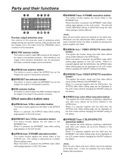
... select the B/PRESET bus as the image to be output to the preview connector. 4 DSK selector button This button is used to select ME preview as the image to the preview connector. Both still and strobe cannot be output to be selected at the same time. ... / VIDEO EFFECTS execution button This applies the mosaic, decay and other video effects set by [Video Effects] to the B/PRESET bus. When it is performed using the time effect settings of the effects. ; When it is pressed, the A/PROG video effect setting page appears on the LCD screen without changing the...
... select the B/PRESET bus as the image to be output to the preview connector. 4 DSK selector button This button is used to select ME preview as the image to the preview connector. Both still and strobe cannot be output to be selected at the same time. ... / VIDEO EFFECTS execution button This applies the mosaic, decay and other video effects set by [Video Effects] to the B/PRESET bus. When it is performed using the time effect settings of the effects. ; When it is pressed, the A/PROG video effect setting page appears on the LCD screen without changing the...
AGMX70 User Guide
Page 9
...parameter display area During positioning, the X/Y/Z parameters are displayed here. = Rotary 2 control This control is used to set the parameter of a selected item. > Rotary 3 control This control is used to set the parameter of a selected item. 6 Pattern number display area The transition and key numbers ... 1 LCD (liquid crystal) display The effect parameters, time settings and other information are shown on the page of the page which are set using the rotary 1, 2, 3, 4 and 5 controls. 5 Time display area The ME, DSK and FADE transition times are displayed here. < Rotary 1 control ...
...parameter display area During positioning, the X/Y/Z parameters are displayed here. = Rotary 2 control This control is used to set the parameter of a selected item. > Rotary 3 control This control is used to set the parameter of a selected item. 6 Pattern number display area The transition and key numbers ... 1 LCD (liquid crystal) display The effect parameters, time settings and other information are shown on the page of the page which are set using the rotary 1, 2, 3, 4 and 5 controls. 5 Time display area The ME, DSK and FADE transition times are displayed here. < Rotary 1 control ...

AGMX70 User Guide
Page 10
...) button This button displays the internal video setting page. 1 2 EVENT RECALL AUDIO EFFECTS ON SET FOLLOW 3 4 1 EVENT RECALL button This button is used to be matched with the video during video ME transition or fading. Parts and their functions 25 1 POS. E> DR D DSK FADE (DSK/fade setting... at the ON position. E AUDIO EFFECTS (audio effect setting page display) button This button displays the audio effect setting page. Its function is used to read out events. 2 EVENT SET button This button is preset for fading on the audio effect setting page are executed. 4 AUDIO FOLLOW...
...) button This button displays the internal video setting page. 1 2 EVENT RECALL AUDIO EFFECTS ON SET FOLLOW 3 4 1 EVENT RECALL button This button is used to be matched with the video during video ME transition or fading. Parts and their functions 25 1 POS. E> DR D DSK FADE (DSK/fade setting... at the ON position. E AUDIO EFFECTS (audio effect setting page display) button This button displays the audio effect setting page. Its function is used to read out events. 2 EVENT SET button This button is preset for fading on the audio effect setting page are executed. 4 AUDIO FOLLOW...
AGMX70 User Guide
Page 11
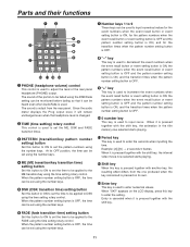
...and the pattern number setting button is ON, and the transition times when the pattern number setting button is OFF. 9 "+" key This key is used to DSK using the time setting rotary control. Example: [2][.][5] > 2 seconds 5 frames When it is pressed together with the shift key, the internal video movie now...FADE transition times. 3 PATTERN (transition/key pattern number setting) button Set this button to ON to set the time to be applied to set using the time setting rotary control. appears on its OFF position, the time can be applied to input zeros. At its own. = Enter key This...
...and the pattern number setting button is ON, and the transition times when the pattern number setting button is OFF. 9 "+" key This key is used to DSK using the time setting rotary control. Example: [2][.][5] > 2 seconds 5 frames When it is pressed together with the shift key, the internal video movie now...FADE transition times. 3 PATTERN (transition/key pattern number setting) button Set this button to ON to set the time to be applied to set using the time setting rotary control. appears on its OFF position, the time can be applied to input zeros. At its own. = Enter key This...
AGMX70 User Guide
Page 12
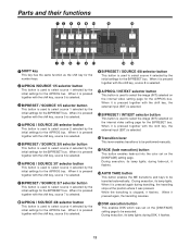
...fade-out, it is pressed together with the shift key, source 7 is selected. 7 B/PRESET / SOURCE 3/7 selector button This button is used to select source 3 selected by the initial settings for the A/PROG bus. When it flashes. > AUTO TAKE button This button enables the ... input (EXT) is selected. ; When it is pressed together with the shift key, source 5 is selected. 4 A/PROG / SOURCE 2/6 selector button This button is used to select source 2 selected by the initial settings for the B/PRESET bus. When it pressed again, the transiting resumes. ? Parts and their functions 12 4 6 8 ...
...fade-out, it is pressed together with the shift key, source 7 is selected. 7 B/PRESET / SOURCE 3/7 selector button This button is used to select source 3 selected by the initial settings for the A/PROG bus. When it flashes. > AUTO TAKE button This button enables the ... input (EXT) is selected. ; When it is pressed together with the shift key, source 5 is selected. 4 A/PROG / SOURCE 2/6 selector button This button is used to select source 2 selected by the initial settings for the B/PRESET bus. When it pressed again, the transiting resumes. ? Parts and their functions 12 4 6 8 ...
AGMX70 User Guide
Page 13
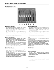
... the higher/lower relationship between them has been reversed when the input has been switched. It executes the effects which have been set are executed using the MASTER fader. Parts and their functions Audio mixer area SOURCE 1 / 5 SOURCE 2 / 6 SOURCE 3 / 7 SOURCE 4 / 8 AUX 1 MAX MIC / AUX 2 MASTER MAX ...MIN MIN 12 3456 7 1 SOURCE 1/5 fader This fader is used to adjust the audio level of input 1 which was set on the initial setting page or of MIC (sound selected by the Audio Effects ON...
... the higher/lower relationship between them has been reversed when the input has been switched. It executes the effects which have been set are executed using the MASTER fader. Parts and their functions Audio mixer area SOURCE 1 / 5 SOURCE 2 / 6 SOURCE 3 / 7 SOURCE 4 / 8 AUX 1 MAX MIC / AUX 2 MASTER MAX ...MIN MIN 12 3456 7 1 SOURCE 1/5 fader This fader is used to adjust the audio level of input 1 which was set on the initial setting page or of MIC (sound selected by the Audio Effects ON...

AGMX70 User Guide
Page 14
... GPI AUX IN 1 2 L R 12 3 4 6 7 EDITOR AUDIO OUT 2 L R 1 External key input connector This connector can be used for source input uses. 5 G/L (genlock reference) input connectors These are loop-through the frame synchronizers, they must be synchronized with advanced vertical phase for key or DSK...) output connector This connector outputs the reference signal with this connector. 7 GPI input connector A trigger is applied and a transition is used when the optional board (AG-YA70) has been installed. 1 MIC input connector This connector can be set on the initial setting page...
... GPI AUX IN 1 2 L R 12 3 4 6 7 EDITOR AUDIO OUT 2 L R 1 External key input connector This connector can be used for source input uses. 5 G/L (genlock reference) input connectors These are loop-through the frame synchronizers, they must be synchronized with advanced vertical phase for key or DSK...) output connector This connector outputs the reference signal with this connector. 7 GPI input connector A trigger is applied and a transition is used when the optional board (AG-YA70) has been installed. 1 MIC input connector This connector can be set on the initial setting page...

AGMX70 User Guide
Page 16
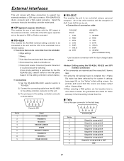
... selected on the initial setting page. 1 4 EDITOR O RS422 SIGNAL GND RS232C 1 TALLY ~AC IN 2 AUDIO OUT 1 R 2 3 5 1 EDITOR interface connector (9-pin) This connector is used to connect the unit with an RS422A or RS-232C controller. 2 RS-422A/RS-232C selector switch This is... used by the cross point is for the cross point 1, 2, 3, 4, 5, 6, 7 or 8 output. voltage: 3.5V) TALLY output GND (Max. The connector used to switch between the RS-422A and RS232C control protocols. 3 SIGNAL GND (ground) terminal ...
... selected on the initial setting page. 1 4 EDITOR O RS422 SIGNAL GND RS232C 1 TALLY ~AC IN 2 AUDIO OUT 1 R 2 3 5 1 EDITOR interface connector (9-pin) This connector is used to connect the unit with an RS422A or RS-232C controller. 2 RS-422A/RS-232C selector switch This is... used by the cross point is for the cross point 1, 2, 3, 4, 5, 6, 7 or 8 output. voltage: 3.5V) TALLY output GND (Max. The connector used to switch between the RS-422A and RS232C control protocols. 3 SIGNAL GND (ground) terminal ...
AGMX70 User Guide
Page 17
...Output for cross point 5 Output for cross point 6 Output for cross point 7 Output for frame accuracy if the time setting is lower than 2 frames. Editing using the RS-422A, RS-232 and GPI interface connectors ≥ The commands are received and then executed 3 frames later. ≥ If, while the 3D ...-232C 25-pin 1 TXD 3 RXD 4 RTS 5 CTS 6 DSR 7 SIG.G 20 DTR AG-MX70 9-pin 1 SPARE 2 RXD 3 TXD 4 DTR 5 SIG.G 6 DSR 9 SPARE [DCE CONNECTION] Use the above conversion with the exception of AUX 1 and AUX 2 can be controlled from the AG-A850 ± Wipe settings ± Mixing ± Auto take...
...Output for cross point 5 Output for cross point 6 Output for cross point 7 Output for frame accuracy if the time setting is lower than 2 frames. Editing using the RS-422A, RS-232 and GPI interface connectors ≥ The commands are received and then executed 3 frames later. ≥ If, while the 3D ...-232C 25-pin 1 TXD 3 RXD 4 RTS 5 CTS 6 DSR 7 SIG.G 20 DTR AG-MX70 9-pin 1 SPARE 2 RXD 3 TXD 4 DTR 5 SIG.G 6 DSR 9 SPARE [DCE CONNECTION] Use the above conversion with the exception of AUX 1 and AUX 2 can be controlled from the AG-A850 ± Wipe settings ± Mixing ± Auto take...

AGMX70 User Guide
Page 19
... selected by the bus setting (see page 56) on the "Setup" initial setting screen and input can be switched directly using the cross point button. *2: ADV REF can also be used as an alternative to the AG-A850 editing controller. 19 System Diagram Example 3 Editing application Through connection VTR RS-422A SDI...
... selected by the bus setting (see page 56) on the "Setup" initial setting screen and input can be switched directly using the cross point button. *2: ADV REF can also be used as an alternative to the AG-A850 editing controller. 19 System Diagram Example 3 Editing application Through connection VTR RS-422A SDI...
AGMX70 User Guide
Page 20
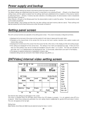
...the power is pressed. If [Demo] has been selected on the [Setup] panel, the demonstration mode is established when the power is not selected using the rotary 1 or 2 control. These settings and data are performed, the color setting mode is turned off . Two lines are allocated to each... LCD display is turned off . The color set appears at a crosspoint. The panel settings, setup settings and their default settings using [Enter]. The demonstration mode can be exited using [Shift] + [.]. [INTVideo] internal video setting screen Wash Pb 128 Pr 128 Y 128 Event ME Time 00E 10:00F ...
...the power is pressed. If [Demo] has been selected on the [Setup] panel, the demonstration mode is established when the power is not selected using the rotary 1 or 2 control. These settings and data are performed, the color setting mode is turned off . Two lines are allocated to each... LCD display is turned off . The color set appears at a crosspoint. The panel settings, setup settings and their default settings using [Enter]. The demonstration mode can be exited using [Shift] + [.]. [INTVideo] internal video setting screen Wash Pb 128 Pr 128 Y 128 Event ME Time 00E 10:00F ...

AGMX70 User Guide
Page 21
...] : Vertical gradation 2 Custom2 [V3] : Vertical gradation 3 [Diag1] : Diagonal gradation 1 [Diag2] : Diagonal gradation 2 The [Grade] combined gradation level is set using the rotary 5 control. There are 10 choices: White, Yellow, Cyan, Green, Magenta, Red, Blue, Black, Custom1 and Custom2. The gradation position is set . The ...color for Custom1 and Custom2 is black. Any value from 16 to 255 but only when [Custom1] or [Custom2] has been selected using rotary 2 control. With Set BackM, the joystick XY and rotary Z control at the top of the screen appear as "Matte,"...
...] : Vertical gradation 2 Custom2 [V3] : Vertical gradation 3 [Diag1] : Diagonal gradation 1 [Diag2] : Diagonal gradation 2 The [Grade] combined gradation level is set using the rotary 5 control. There are 10 choices: White, Yellow, Cyan, Green, Magenta, Red, Blue, Black, Custom1 and Custom2. The gradation position is set . The ...color for Custom1 and Custom2 is black. Any value from 16 to 255 but only when [Custom1] or [Custom2] has been selected using rotary 2 control. With Set BackM, the joystick XY and rotary Z control at the top of the screen appear as "Matte,"...

AGMX70 User Guide
Page 22
..., if pages are to titles, the number of frames for Movie writing. If Still images are allocated to be written appears, write it will be used to a maximum of image writing. ≥ Playback procedure When Frame = 1 R1 Memory R2 Page R3 Frame 1 1 R4 R5 Mode Field Write 1 - ...are to be played back, set a number greater than 1 for Still writing and set the number of frames exceeds the number written using the rotary 3 control, it using the rotary 4 control. If the setting for "Memory." It is turned off. Even when the page selected by the equivalent amount...
..., if pages are to titles, the number of frames for Movie writing. If Still images are allocated to be written appears, write it will be used to a maximum of image writing. ≥ Playback procedure When Frame = 1 R1 Memory R2 Page R3 Frame 1 1 R4 R5 Mode Field Write 1 - ...are to be played back, set a number greater than 1 for Still writing and set the number of frames exceeds the number written using the rotary 3 control, it using the rotary 4 control. If the setting for "Memory." It is turned off. Even when the page selected by the equivalent amount...
AGMX70 User Guide
Page 23
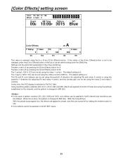
... rotary 5 controls. Preview is 0. The default setting is set to A by pressing the [Color Effects] button for B. When this is done, the pattern is selected using the A or B bus [Color Effects] button. [Color Effects] setting screen Color Pb 128 Pr 128 Effect C Gain 0 Event ME Time 00E 10:00F Pattern 3015...). (With the A bus/B bus) With the preset bus/program bus, the effects are applied to preset, and they are applied to the B or Preset bus using the settings established for this channel, and the pattern is not to be changed to MIX (56). ≥ In the case of the bus to...
... rotary 5 controls. Preview is 0. The default setting is set to A by pressing the [Color Effects] button for B. When this is done, the pattern is selected using the A or B bus [Color Effects] button. [Color Effects] setting screen Color Pb 128 Pr 128 Effect C Gain 0 Event ME Time 00E 10:00F Pattern 3015...). (With the A bus/B bus) With the preset bus/program bus, the effects are applied to preset, and they are applied to the B or Preset bus using the settings established for this channel, and the pattern is not to be changed to MIX (56). ≥ In the case of the bus to...
AGMX70 User Guide
Page 24
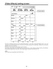
... the status of the [Video Effects] button is not to be changed, press the [Video Effects] button of the bus to be set is selected using the rotary 1 control: [Mosaic], [Defocus], [Mono], [Time Effects], [Decay], [Paint], [Nega], [Mirror] and [3D]. [OFF], [Ripple], [Multi] or [Spark]... can be applied to be set using the A or B bus [Video Effects] button. [Video Effects] setting screen Pos. The following video effects can be selected for the A bus and B bus. Settings can ...
... the status of the [Video Effects] button is not to be changed, press the [Video Effects] button of the bus to be set is selected using the rotary 1 control: [Mosaic], [Defocus], [Mono], [Time Effects], [Decay], [Paint], [Nega], [Mirror] and [3D]. [OFF], [Ripple], [Multi] or [Spark]... can be applied to be set using the A or B bus [Video Effects] button. [Video Effects] setting screen Pos. The following video effects can be selected for the A bus and B bus. Settings can ...

