

AKHC931 User Guide
Page 1
Multi-Format Camera Model AK-HC931P Before attempting to connect, operate or adjust this product, please read these instructions completely.
Multi-Format Camera Model AK-HC931P Before attempting to connect, operate or adjust this product, please read these instructions completely.

AKHC931 User Guide
Page 3
Contents For your safety 2 Overview 4 Features 4 Controls and their functions 5 Mounting the lens 10 Adjusting the lens flange back 11 Performing the viewfinder adjustments 12 Connecting the microphone 14 Mounting the camera on a tripod 15 Component system configuration 16 System connections 1 (with Multi-Format Camera 18 System connections 2 (with build-up unit 19 System connections 3 (with MSU 20 Status displays on viewfinder screen 21 Menu operations 22 Setting menu configuration 24 AK-HC931P Connector pin assignment 27 External dimension drawing 28 Specifications 29 3
Contents For your safety 2 Overview 4 Features 4 Controls and their functions 5 Mounting the lens 10 Adjusting the lens flange back 11 Performing the viewfinder adjustments 12 Connecting the microphone 14 Mounting the camera on a tripod 15 Component system configuration 16 System connections 1 (with Multi-Format Camera 18 System connections 2 (with build-up unit 19 System connections 3 (with MSU 20 Status displays on viewfinder screen 21 Menu operations 22 Setting menu configuration 24 AK-HC931P Connector pin assignment 27 External dimension drawing 28 Specifications 29 3

AKHC931 User Guide
Page 4
...-HRP931P) or MSU (AK-MSU930P), also available as an optional accessory, can be input by combining Panasonic's unique horizontal line readout CCDs with high picture quality featured in the camera unit ≥ After the process circuits, the signals undergo 12-bit, 74 MHz high-picture-quality ...and they achieve a high performance which only digital systems can deliver. Fuller complement of SD. Overview This new-generation all-format HD camera is on a par with a million pixels [1280 (H) x 720 (V)]. By way of providing support for the 720P format, this model uses newly developed 2/3z CCDs...
...-HRP931P) or MSU (AK-MSU930P), also available as an optional accessory, can be input by combining Panasonic's unique horizontal line readout CCDs with high picture quality featured in the camera unit ≥ After the process circuits, the signals undergo 12-bit, 74 MHz high-picture-quality ...and they achieve a high performance which only digital systems can deliver. Fuller complement of SD. Overview This new-generation all-format HD camera is on a par with a million pixels [1280 (H) x 720 (V)]. By way of providing support for the 720P format, this model uses newly developed 2/3z CCDs...

AKHC931 User Guide
Page 6
Controls and their functions V _ PTT RET W X Y Z ^ ] \ [ NAM R G Y /C B FILTER LOCAL MONI SEL 1A ND FILTER CC 1 CAP 3200K A 2 CLEAR 4300K B 3 1 / 4ND 6300K C 4 1/16ND CROSS D 5 1/64ND DF0 E CAM/VTR GAIN ON ON LOW OUTPUT CAM W.BAL B MID BAR A STBY SAVE HIGH TEST PRST PTT USER SEL _` PHANT OFF PHANT OFF AB AB -40 -30 -20 -40 -30 -50 -60 -20 -50 -60 (dB) (dB) MIC1 MIC2 R S U T a F OPT FIBER HD SDI OUT AUX OUT PROMPTER/GL 6 VF E 1 ULTI FORMAT DIGITAL CAMERA SYSTEM MONITOR OUT LENS MIC1 j i
Controls and their functions V _ PTT RET W X Y Z ^ ] \ [ NAM R G Y /C B FILTER LOCAL MONI SEL 1A ND FILTER CC 1 CAP 3200K A 2 CLEAR 4300K B 3 1 / 4ND 6300K C 4 1/16ND CROSS D 5 1/64ND DF0 E CAM/VTR GAIN ON ON LOW OUTPUT CAM W.BAL B MID BAR A STBY SAVE HIGH TEST PRST PTT USER SEL _` PHANT OFF PHANT OFF AB AB -40 -30 -20 -40 -30 -50 -60 -20 -50 -60 (dB) (dB) MIC1 MIC2 R S U T a F OPT FIBER HD SDI OUT AUX OUT PROMPTER/GL 6 VF E 1 ULTI FORMAT DIGITAL CAMERA SYSTEM MONITOR OUT LENS MIC1 j i

AKHC931 User Guide
Page 7
...lever The lens is inserted into the lens mount A, and this pad in response to a call from this connector. A OPT LED This indicates the camera's optical signal reception status. C Lens cable, mic cable clamps These are output from this connector. It also lights in such a way that the ...Multi-Format Camera can be mixed with INCOM1. : INCOM1 PGM level control [INCOM1 PGM] This is pressed. The pad position can be mixed with INCOM2. C Back...
...lever The lens is inserted into the lens mount A, and this pad in response to a call from this connector. A OPT LED This indicates the camera's optical signal reception status. C Lens cable, mic cable clamps These are output from this connector. It also lights in such a way that the ...Multi-Format Camera can be mixed with INCOM1. : INCOM1 PGM level control [INCOM1 PGM] This is pressed. The pad position can be mixed with INCOM2. C Back...

AKHC931 User Guide
Page 8
... status when VTR recording has been temporarily stopped. when it is pressed again, the menu screen display is connected to this switch is pressed, the camera's user menu is used to select the images (Y, NAM, R, G, B] which are to select the video output (CAM, BAR or TEST). A DC 12... to be heard. when it is pressed again, the selected mode is connected to 60 dBm). For details on its operation, refer to the camera. ] Camera output selector switch [OUTPUT] This is output; N Rear MIC2 connector [MIC2] An audio component or microphone is cleared. 8 b Menu switch ...
... status when VTR recording has been temporarily stopped. when it is pressed again, the menu screen display is connected to this switch is pressed, the camera's user menu is used to select the images (Y, NAM, R, G, B] which are to select the video output (CAM, BAR or TEST). A DC 12... to be heard. when it is pressed again, the selected mode is connected to 60 dBm). For details on its operation, refer to the camera. ] Camera output selector switch [OUTPUT] This is output; N Rear MIC2 connector [MIC2] An audio component or microphone is cleared. 8 b Menu switch ...

AKHC931 User Guide
Page 9
... [LENS] The lens cable is connected to this dial button. h Front MIC1 connector [MIC1] A microphone (optional accessory) is connected to the camera. What kind power is to be connected from this connector. It is not effective when the CCU is connected here. Its function can be supplied ... be used as the VTR button of the VTR and return image selector switch. d Electronic shutter selector switch [SHUTTER] This is set to the camera. It performs the same operations as the REC start switch [AUTO W/B BAL] This switch is operated when the white balance (AWB) or black balance...
... [LENS] The lens cable is connected to this dial button. h Front MIC1 connector [MIC1] A microphone (optional accessory) is connected to the camera. What kind power is to be connected from this connector. It is not effective when the CCU is connected here. Its function can be supplied ... be used as the VTR button of the VTR and return image selector switch. d Electronic shutter selector switch [SHUTTER] This is set to the camera. It performs the same operations as the REC start switch [AUTO W/B BAL] This switch is operated when the white balance (AWB) or black balance...

AKHC931 User Guide
Page 10
Flange back adjustment for the lens (performed using the controls on the camera) 3 Lower the lens clamp lever to clamp the lens in place. 10 White shading adjustment for the lens 2. Mounting the lens 1 Raise the lens clamp ... the LENS connector. Mount cap Lens clamp lever LENS connector 2 Align the center mark on the lens mounted, it to perform the following lens and camera adjustments. 1. Auto iris operation speed adjustment for the lens 3. Center mark ≥ For details on handling the lens, refer to the instructions that accompany the...
Flange back adjustment for the lens (performed using the controls on the camera) 3 Lower the lens clamp lever to clamp the lens in place. 10 White shading adjustment for the lens 2. Mounting the lens 1 Raise the lens clamp ... the LENS connector. Mount cap Lens clamp lever LENS connector 2 Align the center mark on the lens mounted, it to perform the following lens and camera adjustments. 1. Auto iris operation speed adjustment for the lens 3. Center mark ≥ For details on handling the lens, refer to the instructions that accompany the...

AKHC931 User Guide
Page 11
... ring may be adjusted again unless the lens is focused properly at a distance of the lens parts, refer also to be performed. Depending on the camera. About 10 ft (3 m) 1 Mount the lens on the lens concerned, this time. 5 Set the zoom ring to the telephoto position either by manual or electrical...
... ring may be adjusted again unless the lens is focused properly at a distance of the lens parts, refer also to be performed. Depending on the camera. About 10 ft (3 m) 1 Mount the lens on the lens concerned, this time. 5 Set the zoom ring to the telephoto position either by manual or electrical...
AKHC931 User Guide
Page 12
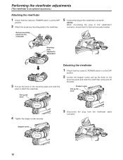
...the viewfinder along and off the plate. Performing the viewfinder adjustments (The viewfinder is an optional accessory.) Attaching the viewfinder 1 Check that the camera's POWER switch is at the OFF position. 2 Attach the accessory mounting plate to the viewfinder. 5 Connect the plug to the viewfinder's...viewfinder cable connector. 12 Stopper screw 3 Disconnect the plug from the viewfinder Mounting plate supplied to the viewfinder's connector, ensure that the camera's POWER switch is at the OFF position. 2 Loosen the stopper screw, pull up the knob on the mounting plate and slide ...
...the viewfinder along and off the plate. Performing the viewfinder adjustments (The viewfinder is an optional accessory.) Attaching the viewfinder 1 Check that the camera's POWER switch is at the OFF position. 2 Attach the accessory mounting plate to the viewfinder. 5 Connect the plug to the viewfinder's...viewfinder cable connector. 12 Stopper screw 3 Disconnect the plug from the viewfinder Mounting plate supplied to the viewfinder's connector, ensure that the camera's POWER switch is at the OFF position. 2 Loosen the stopper screw, pull up the knob on the mounting plate and slide ...

AKHC931 User Guide
Page 14
... holder. 4 If the audio channel whose signals are to be recorded so requires, set the AUDIO IN switch to the MIC IN connector on the camera. Microphone holder 2 Mount the microphone and tighten up the clamp screw. INCOM1 INCOM2 POWER BREAKER RET CONT SEE MANUAL CCU OFF EXT EXT I/O TALLY RCB...
... holder. 4 If the audio channel whose signals are to be recorded so requires, set the AUDIO IN switch to the MIC IN connector on the camera. Microphone holder 2 Mount the microphone and tighten up the clamp screw. INCOM1 INCOM2 POWER BREAKER RET CONT SEE MANUAL CCU OFF EXT EXT I/O TALLY RCB...
AKHC931 User Guide
Page 15
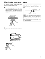
... -40 -30 -50 -60 -20 -50 -60 (dB) (dB) MIC1 MIC2 15 Mounting the camera on a tripod Use the tripod attachment, available as an optional accessory, to its original position after the camera has been detached, push the red lever again and simultaneously move the black lever in mind that... the diameter of the selected holes match the diameter of the camera and tripod together when selecting the holes for attaching the camera. Tripod attachment Red lever Black lever If the pin of the tripod attachment fails to return to its ...
... -40 -30 -50 -60 -20 -50 -60 (dB) (dB) MIC1 MIC2 15 Mounting the camera on a tripod Use the tripod attachment, available as an optional accessory, to its original position after the camera has been detached, push the red lever again and simultaneously move the black lever in mind that... the diameter of the selected holes match the diameter of the camera and tripod together when selecting the holes for attaching the camera. Tripod attachment Red lever Black lever If the pin of the tripod attachment fails to return to its ...

AKHC931 User Guide
Page 16
...OFF CONTROL SHADING BLACK WHITE R G B WHITE BLK KNEE CLIP GAMMA UNDO PED FLAME GAMMA GAIN HD. The basic system configuration includes the lens, Multi-Format Camera, 2z viewfinder, camera control unit (CCU) and remote operation panel (ROP). FACE SD CARD CARD RESET HEAD POWER ALL ALARM REF FILE...be controlled. DTL SD. DTL SD. The MSU (AK-MSU930P) is described below and shown on the following page. System block diagram Large lens Build-up unit AK-HBU931P CABLE TALLY CAMERA 1 2 3 4 5 6 5600K FLARE BLK GAMMA OFF GAMMA ON OFF MODE KNEE OFF WHITE HD. MATRIX CLIP...
...OFF CONTROL SHADING BLACK WHITE R G B WHITE BLK KNEE CLIP GAMMA UNDO PED FLAME GAMMA GAIN HD. The basic system configuration includes the lens, Multi-Format Camera, 2z viewfinder, camera control unit (CCU) and remote operation panel (ROP). FACE SD CARD CARD RESET HEAD POWER ALL ALARM REF FILE...be controlled. DTL SD. DTL SD. The MSU (AK-MSU930P) is described below and shown on the following page. System block diagram Large lens Build-up unit AK-HBU931P CABLE TALLY CAMERA 1 2 3 4 5 6 5600K FLARE BLK GAMMA OFF GAMMA ON OFF MODE KNEE OFF WHITE HD. MATRIX CLIP...

AKHC931 User Guide
Page 17
...fiber cable (optional accessory). Component system configuration Outline of peripheral components 1 Camera control unit (CCU: AK-HCU931P) This is connected to the Multi-Format Camera using the ROP cable (optional accessory), and enables the camera, CCU and lens to be operated when the system is built up unit (AK-... the ROP. 4 2z viewfinder (2zVF: AJ-HVF27P) This is the LCD viewfinder for the Multi-Format Camera. 5 Build-up . After all the components have been connected (the monitor system may be used , the MSU can still be operated by remote control. 3 Master setup unit (MSU:AK...
...fiber cable (optional accessory). Component system configuration Outline of peripheral components 1 Camera control unit (CCU: AK-HCU931P) This is connected to the Multi-Format Camera using the ROP cable (optional accessory), and enables the camera, CCU and lens to be operated when the system is built up unit (AK-... the ROP. 4 2z viewfinder (2zVF: AJ-HVF27P) This is the LCD viewfinder for the Multi-Format Camera. 5 Build-up . After all the components have been connected (the monitor system may be used , the MSU can still be operated by remote control. 3 Master setup unit (MSU:AK...

AKHC931 User Guide
Page 18
System connections 1 (with the connections, set the CCU power switch to the OFF position. 2 Connect the Multi-Format Camera to the CCU. 3 Connect the ROP cable to the CCU and ROP. 4 When the camera power switch is set to ON after the CCU main power switch has been set to ON, the camera...camera power switch and main power switch to OFF. 18 CLOSE BAR TEST WHITE SD CARD AUTO BLACK SET UP CHARACTER RST ALARM OPT FAN CABLE 60Hz MODE FLARE BLK GAMMA AUTO KNEE WHITE MATRIX HD. DTL SD. DTL SD. DTL MATRIX SYSTEM...Before proceeding with Multi-Format Camera) 2z viewfinder AJ-HVF27P Lens...
System connections 1 (with the connections, set the CCU power switch to the OFF position. 2 Connect the Multi-Format Camera to the CCU. 3 Connect the ROP cable to the CCU and ROP. 4 When the camera power switch is set to ON after the CCU main power switch has been set to ON, the camera...camera power switch and main power switch to OFF. 18 CLOSE BAR TEST WHITE SD CARD AUTO BLACK SET UP CHARACTER RST ALARM OPT FAN CABLE 60Hz MODE FLARE BLK GAMMA AUTO KNEE WHITE MATRIX HD. DTL SD. DTL SD. DTL MATRIX SYSTEM...Before proceeding with Multi-Format Camera) 2z viewfinder AJ-HVF27P Lens...

AKHC931 User Guide
Page 19
... (dB) (dB) MIC1 MIC2 CAM/VTR GAIN ON ON LOW OUTPUT CAM W.BAL B MID BAR A STBY SAVE HIGH TEST PRST PTT USER SEL Multi-Format Camera AK-HC931P 8z LCD viewfinder AK-HVF931P CABLE OPEN SHORT ALARM FUSE 125V 5A FUSE 250V 2.5A TALLY/CALL MAIN HEAD POWER LEVEL COXN PGN1... AK-HCU931P ROP cable ROP ON HEAD ON VFPW CAMERA NO. DTL SD. DTL SD. CLOSE BAR TEST WHITE SD CARD AUTO BLACK SET UP CHARACTER RST ALARM OPT FAN CABLE 60Hz MODE FLARE BLK GAMMA AUTO KNEE WHITE MATRIX HD. DTL MATRIX SYSTEM FUNC FILTER ND HEAD CAP 100 25 6.3 1.6 1 SCENE...
... (dB) (dB) MIC1 MIC2 CAM/VTR GAIN ON ON LOW OUTPUT CAM W.BAL B MID BAR A STBY SAVE HIGH TEST PRST PTT USER SEL Multi-Format Camera AK-HC931P 8z LCD viewfinder AK-HVF931P CABLE OPEN SHORT ALARM FUSE 125V 5A FUSE 250V 2.5A TALLY/CALL MAIN HEAD POWER LEVEL COXN PGN1... AK-HCU931P ROP cable ROP ON HEAD ON VFPW CAMERA NO. DTL SD. DTL SD. CLOSE BAR TEST WHITE SD CARD AUTO BLACK SET UP CHARACTER RST ALARM OPT FAN CABLE 60Hz MODE FLARE BLK GAMMA AUTO KNEE WHITE MATRIX HD. DTL MATRIX SYSTEM FUNC FILTER ND HEAD CAP 100 25 6.3 1.6 1 SCENE...

AKHC931 User Guide
Page 20
... PED IRIS RANGE Remote Operation Panel AK-HRP930P Remote operation panel 14 AK-HRP931P ROP ON HEAD ON VFPW CAMERA NO. ROP ON HEAD ON VFPW CAMERA NO. DTL HD.FACE SD. System connections 3 (with MSU) NAM Y /C RG B FILTER LOCAL MONI SEL 1A ND FILTER CC 1 ... POWER LEVEL COXN PGN1 PGN OFF PGN2 PUSH PRIVATE MIC ON OFF PTT Camera control unit 14 AK-HCU931P CABLE TALLY CAMERA 1 2 3 4 5 6 5600K FLARE BLK GAMMA OFF GAMMA ON OFF MODE KNEE OFF WHITE HD. CLIP KNEE HD. DTL MATRIX SYSTEM FUNC FILTER ND HEAD CAP 100 25 6.3 1.6 1 SCENE FILE 2 3 4 ...
... PED IRIS RANGE Remote Operation Panel AK-HRP930P Remote operation panel 14 AK-HRP931P ROP ON HEAD ON VFPW CAMERA NO. ROP ON HEAD ON VFPW CAMERA NO. DTL HD.FACE SD. System connections 3 (with MSU) NAM Y /C RG B FILTER LOCAL MONI SEL 1A ND FILTER CC 1 ... POWER LEVEL COXN PGN1 PGN OFF PGN2 PUSH PRIVATE MIC ON OFF PTT Camera control unit 14 AK-HCU931P CABLE TALLY CAMERA 1 2 3 4 5 6 5600K FLARE BLK GAMMA OFF GAMMA ON OFF MODE KNEE OFF WHITE HD. CLIP KNEE HD. DTL MATRIX SYSTEM FUNC FILTER ND HEAD CAP 100 25 6.3 1.6 1 SCENE FILE 2 3 4 ...

AKHC931 User Guide
Page 21
...voltage output is indicated here in the form of the iris setting (f-number) is being used . : Camera warning or message display: A message indicating the occurrence of an alarm, the camera settings, the progress made , a message with details of the setting, the status of the adjustment ...display 4 Battery voltage display 5 Filter display 6 White balance memory display 7 Gain display 8 Audio CH1 and CH2 displays 9 Iris f-number display : Camera warning or message display ; The setting menu VF DISPLAY screen and the items which has a focus position voltage output is displayed here. When a ...
...voltage output is indicated here in the form of the iris setting (f-number) is being used . : Camera warning or message display: A message indicating the occurrence of an alarm, the camera settings, the progress made , a message with details of the setting, the status of the adjustment ...display 4 Battery voltage display 5 Filter display 6 White balance memory display 7 Gain display 8 Audio CH1 and CH2 displays 9 Iris f-number display : Camera warning or message display ; The setting menu VF DISPLAY screen and the items which has a focus position voltage output is displayed here. When a ...

AKHC931 User Guide
Page 22
... Mark 13:9 Safety Mark 16:9 Center Mark OFF Center Mark Sel 1 Line Width 4 3 Turn the JOG dial to the flashing will remain unchanged. 22 The camera's USER menu screen now appears on the viewfinder or monitor. VF Setting1 Side Modulation 15 Zone Mark 4:3 Safety Mark 16:9 Center Mark OFF Center Mark...
... Mark 13:9 Safety Mark 16:9 Center Mark OFF Center Mark Sel 1 Line Width 4 3 Turn the JOG dial to the flashing will remain unchanged. 22 The camera's USER menu screen now appears on the viewfinder or monitor. VF Setting1 Side Modulation 15 Zone Mark 4:3 Safety Mark 16:9 Center Mark OFF Center Mark...

AKHC931 User Guide
Page 24
... Viewfinder settings1 VF Setting2 Viewfinder settings2 VF Display1 Viewfinder display settings VF Display2 Viewfinder display settings Setting1 Camera settings1 Setting2 Camera settings2 Setting3 Camera settings3 INCOM INCOM settings !LED Camera status display settings 24 7"VF Side Modulation (for changing the brightness level of the signals outside the... the gain SW to MID gain) GAIN SW HIGH (for setting the gain SW to HIGH gain) ID NUMBER (for setting the camera number and designation) CH1 ENG/PD (for switching INCOM1) CH2 ENG/PD (for switching INCOM2) CH1 CCU/CRANE (for switching crane...
... Viewfinder settings1 VF Setting2 Viewfinder settings2 VF Display1 Viewfinder display settings VF Display2 Viewfinder display settings Setting1 Camera settings1 Setting2 Camera settings2 Setting3 Camera settings3 INCOM INCOM settings !LED Camera status display settings 24 7"VF Side Modulation (for changing the brightness level of the signals outside the... the gain SW to MID gain) GAIN SW HIGH (for setting the gain SW to HIGH gain) ID NUMBER (for setting the camera number and designation) CH1 ENG/PD (for switching INCOM1) CH2 ENG/PD (for switching INCOM2) CH1 CCU/CRANE (for switching crane...


