

BMET200 User Guide
Page 1
The model numbers in these instructions carefully and save this product, please read these Operating Instructions are given without suffix. reject BM-ET200 accept Before attempting to connect or operate this manual for future use. Iris Reader Operating Instructions BM-ET200 Model No.
The model numbers in these instructions carefully and save this product, please read these Operating Instructions are given without suffix. reject BM-ET200 accept Before attempting to connect or operate this manual for future use. Iris Reader Operating Instructions BM-ET200 Model No.
BMET200 User Guide
Page 2
... of the unit. Cautions: • This unit is intended to alert the user to UL Listed Access Control Panels installation instructions for compatibility information with Iris Reader, Model BM-ET200. SA 1966 2 The exclamation point within an equilateral triangle is for indoor use only. • Refer to the name plate on the...
... of the unit. Cautions: • This unit is intended to alert the user to UL Listed Access Control Panels installation instructions for compatibility information with Iris Reader, Model BM-ET200. SA 1966 2 The exclamation point within an equilateral triangle is for indoor use only. • Refer to the name plate on the...
BMET200 User Guide
Page 6
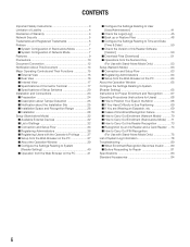
...45 I Back up or Restore Files 48 I Configure the Settings Relating to Time and Date [Time & Date 50 I Check the Version of Iris Reader Software [Version 50 I Download Files [Download 51 I Operations from the Numeric Key (For Use with Stand-Alone Mode Only 53 Setup (Network ... Mode 70 I How to Carry Out Enrollment (Stand-alone Mode) .....71 I How to Carry Out Iris Reader Recognition 73 I Recognition by an Iris Reader and a Card Reader ....74 I How to Carry Out PIN Recognition (For Use with Stand-Alone Mode Only 75 List of System Log Information 78 Troubleshooting 80 I When Enrollment...
...45 I Back up or Restore Files 48 I Configure the Settings Relating to Time and Date [Time & Date 50 I Check the Version of Iris Reader Software [Version 50 I Download Files [Download 51 I Operations from the Numeric Key (For Use with Stand-Alone Mode Only 53 Setup (Network ... Mode 70 I How to Carry Out Enrollment (Stand-alone Mode) .....71 I How to Carry Out Iris Reader Recognition 73 I Recognition by an Iris Reader and a Card Reader ....74 I How to Carry Out PIN Recognition (For Use with Stand-Alone Mode Only 75 List of System Log Information 78 Troubleshooting 80 I When Enrollment...
BMET200 User Guide
Page 7
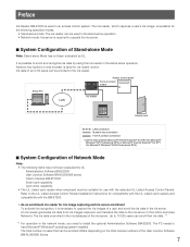
... users can be suitable for use with the BM-ET200. • As an enrollment iris reader for iris image capturing and iris server enrollment To activate iris recognition, it is necessary to have not been evaluated by UL. The iris reader, which captures a user's iris image, is available for Microsoft® Windows® 2000 Professional SP4). I System Configuration of...
... users can be suitable for use with the BM-ET200. • As an enrollment iris reader for iris image capturing and iris server enrollment To activate iris recognition, it is necessary to have not been evaluated by UL. The iris reader, which captures a user's iris image, is available for Microsoft® Windows® 2000 Professional SP4). I System Configuration of...
BMET200 User Guide
Page 8
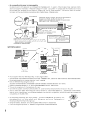
... Access control panel *8 DB Administration software LAN LAN Wiegand/RS-485 Wiegand/ RS-485 Access control server *8 LAN Iris reader (for Recognition) Card reader *8 Wiegand/RS-485 Electric lock Iris reader (for Enrollment) Wiegand/ RS-485 Iris reader (for Recognition) Card reader *8 *2 The recognition time may differ depending on available cards and card writers. *5 Capturing diagnosis is made by checking the...
... Access control panel *8 DB Administration software LAN LAN Wiegand/RS-485 Wiegand/ RS-485 Access control server *8 LAN Iris reader (for Recognition) Card reader *8 Wiegand/RS-485 Electric lock Iris reader (for Enrollment) Wiegand/ RS-485 Iris reader (for Recognition) Card reader *8 *2 The recognition time may differ depending on available cards and card writers. *5 Capturing diagnosis is made by checking the...
BMET200 User Guide
Page 9
... is within 50 cm {1.64 ft.} of the front of a user by connecting this document, the certification by the card reader connected to the iris reader. Iris readers and the iris server can be directly connected to an iris reader, recognition is available. 9 Any card reader supporting the Wiegand/RS-485 interface can compose an access control system in the...
... is within 50 cm {1.64 ft.} of the front of a user by connecting this document, the certification by the card reader connected to the iris reader. Iris readers and the iris server can be directly connected to an iris reader, recognition is available. 9 Any card reader supporting the Wiegand/RS-485 interface can compose an access control system in the...
BMET200 User Guide
Page 11
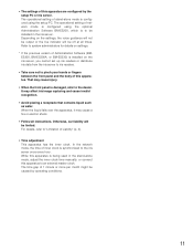
...shock. • Follow all times. For details, refer to the iris server once every hour. While this apparatus. Depending on the iris server, you cannot set up iris readers or distribute iris data from the iris server to iris readers. • Take care not to the dealer. Otherwise, our liability... using the optional Administration Software BM-ES200, which is being used in the iris server. When the liquid falls over the apparatus, it may affect iris image capturing and cause invalid recognition. • Avoid placing a receptacle that contains liquid such as water. The...
...shock. • Follow all times. For details, refer to the iris server once every hour. While this apparatus. Depending on the iris server, you cannot set up iris readers or distribute iris data from the iris server to iris readers. • Take care not to the dealer. Otherwise, our liability... using the optional Administration Software BM-ES200, which is being used in the iris server. When the liquid falls over the apparatus, it may affect iris image capturing and cause invalid recognition. • Avoid placing a receptacle that contains liquid such as water. The...
BMET200 User Guide
Page 12
... when iris recognition is unavailable. Then, the iris data is transferred to 25 users can be used in the stand-alone operation. Registration from the iris images captured. The total number of certification can be connected. ID data: The data, which is enrolled with each user's information in an access control system with a card reader Iris reader: Panasonic Iris Reader...
... when iris recognition is unavailable. Then, the iris data is transferred to 25 users can be used in the stand-alone operation. Registration from the iris images captured. The total number of certification can be connected. ID data: The data, which is enrolled with each user's information in an access control system with a card reader Iris reader: Panasonic Iris Reader...
BMET200 User Guide
Page 13
.... Iris recognition is available. 13 are registered given without privilege in the administrator mode. Only the enrolled administrator can enter shift from the recognition mode to the administrator mode to the iris reader. ...Numeric key control: Setting change and control of at least one user with the ID and password. Users with the iris reader is available in the stand-alone mode only. Iris reader setup and iris and data enrollment, etc. Web browser control: Iris reader setup is available from the iris reader...
.... Iris recognition is available. 13 are registered given without privilege in the administrator mode. Only the enrolled administrator can enter shift from the recognition mode to the administrator mode to the iris reader. ...Numeric key control: Setting change and control of at least one user with the ID and password. Users with the iris reader is available in the stand-alone mode only. Iris reader setup and iris and data enrollment, etc. Web browser control: Iris reader setup is available from the iris reader...
BMET200 User Guide
Page 14
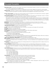
To read PDF documents, you need to install Adobe® Reader®, which you can obtain at the homepage of recognition iris readers do not have to Administration Software BM-ES200, which is supplied with Administration Software BM-ES200. Normally, users of Adobe Systems Incorporated. 14 To use ...
To read PDF documents, you need to install Adobe® Reader®, which you can obtain at the homepage of recognition iris readers do not have to Administration Software BM-ES200, which is supplied with Administration Software BM-ES200. Normally, users of Adobe Systems Incorporated. 14 To use ...
BMET200 User Guide
Page 15
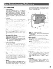
... 25 mm {0.98 in the iris reader. That may damage the audio volume controller. It is removed at the time of installation, connection or maintenance. Note: Avoid adding excessive force to use a Phillips screwdriver that guides a user's position and gives the recognition result. w Front panel Eye...indicator When a user comes within 50 cm {1.64 ft.} of the front of an iris reader, this indicator will light up when recognition is used for eye positioning at the time of iris data enrollment/recognition. Refer to be set to be opened.) 15 Or avoid placing smudges on the settings....
... 25 mm {0.98 in the iris reader. That may damage the audio volume controller. It is removed at the time of installation, connection or maintenance. Note: Avoid adding excessive force to use a Phillips screwdriver that guides a user's position and gives the recognition result. w Front panel Eye...indicator When a user comes within 50 cm {1.64 ft.} of the front of an iris reader, this indicator will light up when recognition is used for eye positioning at the time of iris data enrollment/recognition. Refer to be set to be opened.) 15 Or avoid placing smudges on the settings....
BMET200 User Guide
Page 18
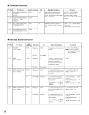
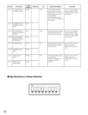
... Interface PWR Wiegand I /O q-1 RECOGNITION RESULT RLT1 OUTPUT 1 ACCEPT OUT q-2 RECOGNITION RESULT GND OUTPUT 1 GND ACCEPT q-3 RECOGNITION START TRG IN TRIGGER INTPUT q-4 RECOGNITION START GND TRIGGER INTPUT GND Signal Description Recognition result output 1 This terminal is activated when recognition is the ground terminal for the power supply and communication between the iris reader and a card reader. G Connector Terminal Pin No...
... Interface PWR Wiegand I /O q-1 RECOGNITION RESULT RLT1 OUTPUT 1 ACCEPT OUT q-2 RECOGNITION RESULT GND OUTPUT 1 GND ACCEPT q-3 RECOGNITION START TRG IN TRIGGER INTPUT q-4 RECOGNITION START GND TRIGGER INTPUT GND Signal Description Recognition result output 1 This terminal is activated when recognition is the ground terminal for the power supply and communication between the iris reader and a card reader. G Connector Terminal Pin No...
BMET200 User Guide
Page 19
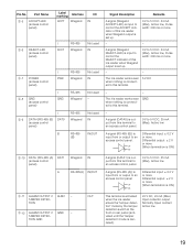
...-485 Wiegand Not used IN RS-485 (B) IN/OUT Signal Description Remarks A signal (Wiegand ACCEPT-LED) is input to control the ACCEPT indicator of this iris reader when Wiegand output is set up. − 0 V to 5 V DC, 24 mA (Max), Active low, Pulse width: 200 ms or more − A signal (...canceled). 24 V DC, 24 mA (Max) Open collector output Normally Open contact Active low 19 TION GND OUT This terminal is activated when the iris reader enters the "tamper detection" mode by the tamper detection switch at the front or rear panel (activated until the "tamper detection" mode is ON) ...
...-485 Wiegand Not used IN RS-485 (B) IN/OUT Signal Description Remarks A signal (Wiegand ACCEPT-LED) is input to control the ACCEPT indicator of this iris reader when Wiegand output is set up. − 0 V to 5 V DC, 24 mA (Max), Active low, Pulse width: 200 ms or more − A signal (...canceled). 24 V DC, 24 mA (Max) Open collector output Normally Open contact Active low 19 TION GND OUT This terminal is activated when the iris reader enters the "tamper detection" mode by the tamper detection switch at the front or rear panel (activated until the "tamper detection" mode is ON) ...
BMET200 User Guide
Page 20
...iris reader. Port Name w-13 ALARM OUTPUT 1 POWER STATUS Label marking Interface ALM1 − I Specifications of Setup Switches ON 1234 5678 20 The terminal is opened when the power supply is shut down. 24 V DC, 24 mA (Max) Open collector output Normally Close contact (Low level) This terminal is activated when recognition... width: 100 ms or more I /O OUT w-14 ALARM OUTPUT 1 GND − POWER STATUS GND w-15 RECOGNITION RLT2 − RESULT OUTPUT 2 REJECT w-16 RECOGNITION GND − RESULT OUTPUT 2 GND REJECT w-17 BUZZER INPUT BUZZ − w-18 BUZZER INPUT GND w-19 ...
...iris reader. Port Name w-13 ALARM OUTPUT 1 POWER STATUS Label marking Interface ALM1 − I Specifications of Setup Switches ON 1234 5678 20 The terminal is opened when the power supply is shut down. 24 V DC, 24 mA (Max) Open collector output Normally Close contact (Low level) This terminal is activated when recognition... width: 100 ms or more I /O OUT w-14 ALARM OUTPUT 1 GND − POWER STATUS GND w-15 RECOGNITION RLT2 − RESULT OUTPUT 2 REJECT w-16 RECOGNITION GND − RESULT OUTPUT 2 GND REJECT w-17 BUZZER INPUT BUZZ − w-18 BUZZER INPUT GND w-19 ...
BMET200 User Guide
Page 21
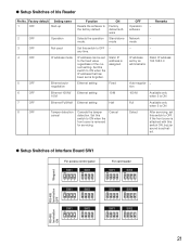
... can be set is forgotten. Ethernet setting Fixed Ethernet setting 10 M Ethernet setting Half 8 OFF Tamper detection cancel Cancels the tamper detection. G Setup Switches of Iris Reader Pin No. mode Set this switch to ON when the front cover is ON Detect After servicing, set this switch to ON when the IP... OFF For access control panel SW1 ON 1234 SW2 ON 1234 SW1 ON 1234 SW2 ON 1234 SW1 ON 1234 SW2 ON 1234 For card reader SW1 ON 1234 SW2 ON 1234 SW1 ON 1234 SW2 ON 1234 SW1 ON 1234 SW2 ON 1234 RS-485 termination ON 21 Static IP...
... can be set is forgotten. Ethernet setting Fixed Ethernet setting 10 M Ethernet setting Half 8 OFF Tamper detection cancel Cancels the tamper detection. G Setup Switches of Iris Reader Pin No. mode Set this switch to ON when the front cover is ON Detect After servicing, set this switch to ON when the IP... OFF For access control panel SW1 ON 1234 SW2 ON 1234 SW1 ON 1234 SW2 ON 1234 SW1 ON 1234 SW2 ON 1234 For card reader SW1 ON 1234 SW2 ON 1234 SW1 ON 1234 SW2 ON 1234 SW1 ON 1234 SW2 ON 1234 RS-485 termination ON 21 Static IP...
BMET200 User Guide
Page 23
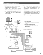
... are independent to control door directly. After the installation, secure the iris reader to disable operation during tamper alarm. Refer to p. 28. • The UL Listed card reader when employed must be suitable for compatibility with the UL Listed card readers and compatibility with the BMET200. • The use relay out to BM-ET200. *3 This...
... are independent to control door directly. After the installation, secure the iris reader to disable operation during tamper alarm. Refer to p. 28. • The UL Listed card reader when employed must be suitable for compatibility with the UL Listed card readers and compatibility with the BMET200. • The use relay out to BM-ET200. *3 This...
BMET200 User Guide
Page 24
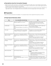
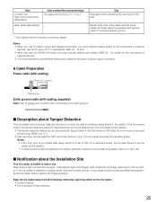
...devices. • When the front cover is removed from an iris reader or the iris reader is removed from the wall, an alarm signal is sent from the alarm output 2 (tamper detection) to alarm devices. • When recognition is not successfully completed, an alarm signal is necessary.) 24... jacket of the cable with BNC plugs. Then, the digital disk recorder automatically records the images output from the recognition result output 2 (REJECT) to the iris reader Solder both ends with M3 screw clamp terminals. G Preparing the Necessary Items Item Power cable (Mandatory) Item number...
...devices. • When the front cover is removed from an iris reader or the iris reader is removed from the wall, an alarm signal is sent from the alarm output 2 (tamper detection) to alarm devices. • When recognition is not successfully completed, an alarm signal is necessary.) 24... jacket of the cable with BNC plugs. Then, the digital disk recorder automatically records the images output from the recognition result output 2 (REJECT) to the iris reader Solder both ends with M3 screw clamp terminals. G Preparing the Necessary Items Item Power cable (Mandatory) Item number...
BMET200 User Guide
Page 25
...ends of stored data is removed for a specified period, the iris data stored in the iris reader will be canceled with M3 screw clamp terminals. The iris reader becomes the operation status. If the iris reader is installed in sunlight, incandescent light and halogen light) is used... capturing by the tamper detection, backup of the cable with Setup Switch 8. Otherwise, light may cause invalid iris data enrollment/recognition, as the iris reader cannot capture iris images properly. Near-infrared light (contained in a place which receives this switch to OFF, and close the...
...ends of stored data is removed for a specified period, the iris data stored in the iris reader will be canceled with M3 screw clamp terminals. The iris reader becomes the operation status. If the iris reader is installed in sunlight, incandescent light and halogen light) is used... capturing by the tamper detection, backup of the cable with Setup Switch 8. Otherwise, light may cause invalid iris data enrollment/recognition, as the iris reader cannot capture iris images properly. Near-infrared light (contained in a place which receives this switch to OFF, and close the...
BMET200 User Guide
Page 26
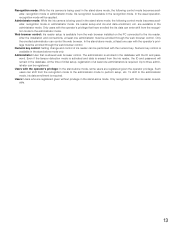
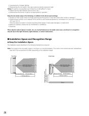
...8226; Places whose humidity is not between 30 % and 90 % and whose temperature is not between 0 °C and +40 °C {between an iris reader and a user, enrollment or recognition may cause damage or a malfunction. • Noise (for example, places near the light reflection (from obstructions 400 mm {16 in.} 700 mm {28...) • Electricity When objects made of light is a recommendation. Top View Side View 400 mm {16 in.} 400 mm {16 in.} Height of the iris reader 1 240 mm {48.8 in.} or more (recommended) 700 mm {28 in.} 700 mm {28 in.} Keep this area free from obstructions 400 mm {...
...8226; Places whose humidity is not between 30 % and 90 % and whose temperature is not between 0 °C and +40 °C {between an iris reader and a user, enrollment or recognition may cause damage or a malfunction. • Noise (for example, places near the light reflection (from obstructions 400 mm {16 in.} 700 mm {28...) • Electricity When objects made of light is a recommendation. Top View Side View 400 mm {16 in.} 400 mm {16 in.} Height of the iris reader 1 240 mm {48.8 in.} or more (recommended) 700 mm {28 in.} 700 mm {28 in.} Keep this area free from obstructions 400 mm {...
BMET200 User Guide
Page 27
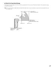
G Check the Capturing Range. If the height of the iris reader unit 12 mm {0.47 in the previous "Side View" illustration, the recognition range will become as described in .} 0 27 If your eye position is higher than the downside limit, get on a pedestal, etc. 1 678 mm {66.1 in.} ... mm {12 in.} 1 395 mm {54.9 in.} Center of optical axis (Recommended installation height) 400 mm {15.7 in.} 1 240 mm {48.8 in.} Bottom of the iris reader is lower than the upside limit, bend down. Note: If your eye position is 1 240 mm {48.8 in.} as follows.
G Check the Capturing Range. If the height of the iris reader unit 12 mm {0.47 in the previous "Side View" illustration, the recognition range will become as described in .} 0 27 If your eye position is higher than the downside limit, get on a pedestal, etc. 1 678 mm {66.1 in.} ... mm {12 in.} 1 395 mm {54.9 in.} Center of optical axis (Recommended installation height) 400 mm {15.7 in.} 1 240 mm {48.8 in.} Bottom of the iris reader is lower than the upside limit, bend down. Note: If your eye position is 1 240 mm {48.8 in.} as follows.