
WVCL930 User Guide
Page 1
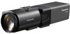
WV-CL934 2X6~1W2mVTm-VLZ1L8:E10N./42S (Lens: option) Before attempting to connect or operate this product, please read these instructions carefully and save this manual. No model number suffix is shown in this manual for future use. Color CCTV Cameras Operating Instructions WV-CL930 Model Nos.
WV-CL934 2X6~1W2mVTm-VLZ1L8:E10N./42S (Lens: option) Before attempting to connect or operate this product, please read these instructions carefully and save this manual. No model number suffix is shown in this manual for future use. Color CCTV Cameras Operating Instructions WV-CL930 Model Nos.

WVCL930 User Guide
Page 3
...-and-white mode [BW MODE 40 12. Image horizontal flip [MIRROR] ......... 43 14. Gain control setting [AGC 29 5. Camera title setting [CAMERA ID] ...... 23 2. Synchronization setting [SYNC 31 7. Image resolution setting [RESOLUTION 40 11. Privacy zone setting [PRIVACY ZONE 42..... 47 Chroma phase level (hue) adjustment [HUE 48 Pixel compensation [PIX OFF 48 Communication configuration [COMMUNICATION 49 Default restoring [CAMERA RESET] ....... 49 Serial number viewing [SER.NO 49 Language Selection [LANGUAGE SETUP 50 Shortcut Operation 51 Troubleshooting 52 Specifications 54 ...
...-and-white mode [BW MODE 40 12. Image horizontal flip [MIRROR] ......... 43 14. Gain control setting [AGC 29 5. Camera title setting [CAMERA ID] ...... 23 2. Synchronization setting [SYNC 31 7. Image resolution setting [RESOLUTION 40 11. Privacy zone setting [PRIVACY ZONE 42..... 47 Chroma phase level (hue) adjustment [HUE 48 Pixel compensation [PIX OFF 48 Communication configuration [COMMUNICATION 49 Default restoring [CAMERA RESET] ....... 49 Serial number viewing [SER.NO 49 Language Selection [LANGUAGE SETUP 50 Shortcut Operation 51 Troubleshooting 52 Specifications 54 ...
WVCL930 User Guide
Page 5
... CLAIM OR ACTION FOR DAMAGES, BROUGHT BY ANY PERSON OR ORGANIZATION BEING A PHOTOGENIC SUBJECT, DUE TO VIOLATION OF PRIVACY WITH THE RESULT OF THAT SURVEILLANCE-CAMERA'S PICTURE, INCLUDING SAVED DATA, FOR SOME REASON, BECOMES PUBLIC OR IS USED FOR THE PURPOSE OTHER THAN SURVEILLANCE. 5 ING WHEN IMAGES ARE NOT DIS- NANCE...
... CLAIM OR ACTION FOR DAMAGES, BROUGHT BY ANY PERSON OR ORGANIZATION BEING A PHOTOGENIC SUBJECT, DUE TO VIOLATION OF PRIVACY WITH THE RESULT OF THAT SURVEILLANCE-CAMERA'S PICTURE, INCLUDING SAVED DATA, FOR SOME REASON, BECOMES PUBLIC OR IS USED FOR THE PURPOSE OTHER THAN SURVEILLANCE. 5 ING WHEN IMAGES ARE NOT DIS- NANCE...

WVCL930 User Guide
Page 6
... If motion is observed in case. 6 Auto back focus function (ABF) equipped Moving the CCD inside the camera to automatically adjust the back focus. Note: The motion detector function is a 1/2-inch type {1/2"} CCD color CCTV camera. Preface This product is not exclusively used for prevention of theft, fire, etc. Night monochrome image activation function...
... If motion is observed in case. 6 Auto back focus function (ABF) equipped Moving the CCD inside the camera to automatically adjust the back focus. Note: The motion detector function is a 1/2-inch type {1/2"} CCD color CCTV camera. Preface This product is not exclusively used for prevention of theft, fire, etc. Night monochrome image activation function...
WVCL930 User Guide
Page 8
.... Make sure that the installation area is not in use .) • Locations subject to mount this product. Be sure to fix this product with the camera mounting base. Radio interference When this product is 12 V DC/24 V AC (WV-CL934) or 120 V AC (WV-CL930). Mounting screws Only the fixing screws...
.... Make sure that the installation area is not in use .) • Locations subject to mount this product. Be sure to fix this product with the camera mounting base. Radio interference When this product is 12 V DC/24 V AC (WV-CL934) or 120 V AC (WV-CL930). Mounting screws Only the fixing screws...

WVCL930 User Guide
Page 10
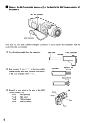
... are used, the side cover is connected to this terminal. 10 w ALC lens connector The ALC connector is on either top or bottom of the camera head. (Tripod socket hole: 1/4-20 UNC for WV-CL934) The power supply of 24 V AC or 12 V DC is used to mount the... camera mounting base (option). i Power indicator This indicator lights up when the power is connected to perform various settings in the setup menu. If the connector ...
... are used, the side cover is connected to this terminal. 10 w ALC lens connector The ALC connector is on either top or bottom of the camera head. (Tripod socket hole: 1/4-20 UNC for WV-CL934) The power supply of 24 V AC or 12 V DC is used to mount the... camera mounting base (option). i Power indicator This indicator lights up when the power is connected to perform various settings in the setup menu. If the connector ...
WVCL930 User Guide
Page 12
Lens cable Approx. 8 mm Approx. 6 mm e Solder the core wires to the ALC lens connector of the camera. q Cut off the lens cable from the connector. Pin 1: Red (Power) Pin 2: Not used , replace the connector with a different shaped connector is used Pin 3: White (...
Lens cable Approx. 8 mm Approx. 6 mm e Solder the core wires to the ALC lens connector of the camera. q Cut off the lens cable from the connector. Pin 1: Red (Power) Pin 2: Not used , replace the connector with a different shaped connector is used Pin 3: White (...
WVCL930 User Guide
Page 13
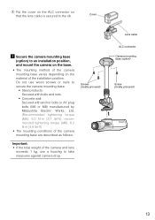
... base varies depending on the ALC connector so that the lens cable is secured to take measures against camera drop. Do not use wood screws or nails to secure the camera mounting base. • Steel products: Secured with bolts and nuts • Concrete wall: Secured with anchor bolts or AY ...Works, Ltd. (Recommended tightening torque (M6): 5.0 N·m {3.7 lbf·ft}, recommended tightening torque (M8): 6.2 N·m {4.6 lbf·ft} • The mounting conditions of the camera mounting base are described as follows: Screws (locally procured) Important: • If the total weight of the...
... base varies depending on the ALC connector so that the lens cable is secured to take measures against camera drop. Do not use wood screws or nails to secure the camera mounting base. • Steel products: Secured with bolts and nuts • Concrete wall: Secured with anchor bolts or AY ...Works, Ltd. (Recommended tightening torque (M6): 5.0 N·m {3.7 lbf·ft}, recommended tightening torque (M8): 6.2 N·m {4.6 lbf·ft} • The mounting conditions of the camera mounting base are described as follows: Screws (locally procured) Important: • If the total weight of the...

WVCL930 User Guide
Page 14
... (VBS/VS) Coaxial cables (locally procured) 120V ~ 60Hz GEN-LOCK VIDEO OUT POWER ALARM GND OUT DAY/ GND NIGHT IN To video input (CAMERA IN) (This illustration represents WV-CL930.) Important: • Be sure to the video output connector. The mounting conditions are the same even for the... coaxial cable to use the screws that were removed from the tripod socket. If the synchronizing signal input is mounted on the top of the camera, be sure to the external synchronization input connector. Use of longer or shorter screws may cause drop or damage. (Recommended tightening torque: 0.39...
... (VBS/VS) Coaxial cables (locally procured) 120V ~ 60Hz GEN-LOCK VIDEO OUT POWER ALARM GND OUT DAY/ GND NIGHT IN To video input (CAMERA IN) (This illustration represents WV-CL930.) Important: • Be sure to the video output connector. The mounting conditions are the same even for the... coaxial cable to use the screws that were removed from the tripod socket. If the synchronizing signal input is mounted on the top of the camera, be sure to the external synchronization input connector. Use of longer or shorter screws may cause drop or damage. (Recommended tightening torque: 0.39...

WVCL930 User Guide
Page 15
... power cord. 120 V AC, 60 Hz Power cord (accessory) 120V ~ 50Hz GEN-LOCK VIDEO OUT POWER ALARM GND OUT DAY/ GND NIGHT IN Caution: The camera shall be connected with cord set with plug. n Connect the power cord and turn on the rear side of metallic or durable material to be... tied to the camera mounting base. Camera mounting base (option) The cable shall be mounted on the Power cord by a qualified electrical. 15 Plug for respective country shall be tied to...
... power cord. 120 V AC, 60 Hz Power cord (accessory) 120V ~ 50Hz GEN-LOCK VIDEO OUT POWER ALARM GND OUT DAY/ GND NIGHT IN Caution: The camera shall be connected with cord set with plug. n Connect the power cord and turn on the rear side of metallic or durable material to be... tied to the camera mounting base. Camera mounting base (option) The cable shall be mounted on the Power cord by a qualified electrical. 15 Plug for respective country shall be tied to...

WVCL930 User Guide
Page 16
... • Reset the back focus position to the CS mount default position before the back focus adjustment. (Press the right and left buttons simultaneously after camera angle adjustment. , Adjust the focus. Use of "ABF" of "BACK-FOCUS SETUP" in the setup menu ( page 45) allows users to adjust the focus optimally.... WV-CL934 Select either 24 V AC or 12 V DC for power supply and connect the power supply to loosen the screw of the camera mounting base when the camera angle is adjusted. When an auto iris lens is used, the originally adjusted focus may be slightly off state can be used. 16...
... • Reset the back focus position to the CS mount default position before the back focus adjustment. (Press the right and left buttons simultaneously after camera angle adjustment. , Adjust the focus. Use of "ABF" of "BACK-FOCUS SETUP" in the setup menu ( page 45) allows users to adjust the focus optimally.... WV-CL934 Select either 24 V AC or 12 V DC for power supply and connect the power supply to loosen the screw of the camera mounting base when the camera angle is adjusted. When an auto iris lens is used, the originally adjusted focus may be slightly off state can be used. 16...

WVCL930 User Guide
Page 18
... the connector, select "G/L 75 Ω". Alarm output Output specification: Open collector output (max. voltage: 16 V DC) Off: 2 to 4 V DC, internally pulled up ) Color: Open or 3 to 5 V DC Black and white: Make contact with GND (required drive current: 0.2 mA or more) ALARM GND OUT DAY/ GND NIGHT IN GND...and WV-CL934. * When color input or black-and-white input is enabled, set the black-and-white switching, "BW MODE" to "EXT". ( page 40) * When an external device is provided to the external synchronization input connector on the rear side of the camera for the normal situation, too....
... the connector, select "G/L 75 Ω". Alarm output Output specification: Open collector output (max. voltage: 16 V DC) Off: 2 to 4 V DC, internally pulled up ) Color: Open or 3 to 5 V DC Black and white: Make contact with GND (required drive current: 0.2 mA or more) ALARM GND OUT DAY/ GND NIGHT IN GND...and WV-CL934. * When color input or black-and-white input is enabled, set the black-and-white switching, "BW MODE" to "EXT". ( page 40) * When an external device is provided to the external synchronization input connector on the rear side of the camera for the normal situation, too....

WVCL930 User Guide
Page 19
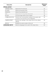
... setting regarding the black-and-white mode such as switching between color and blackand-white images. Selects the drive control type in accordance with the lens to ENGLISH. Setup menu list Setup item CAMERA SETUP CAMERA ID ALC/ELC SHUTTER AGC SENS UP SYNC WHITE BAL MOTION...controlling the quantity of image resolution. Specifies the synchronization type. Selects the motion detector mode. Selects the level of light in the camera shooting area. Specifies the electronic shutter speed. Flips images horizontally. Setup Menus Performing each setting item in the setup menu should be...
... setting regarding the black-and-white mode such as switching between color and blackand-white images. Selects the drive control type in accordance with the lens to ENGLISH. Setup menu list Setup item CAMERA SETUP CAMERA ID ALC/ELC SHUTTER AGC SENS UP SYNC WHITE BAL MOTION...controlling the quantity of image resolution. Specifies the synchronization type. Selects the motion detector mode. Selects the level of light in the camera shooting area. Specifies the electronic shutter speed. Flips images horizontally. Setup Menus Performing each setting item in the setup menu should be...
WVCL930 User Guide
Page 20
.... Reference pages 47 47 47 48 48 49 49 49 50 20 Setup item SPECIAL SETUP CHROMA GAIN AP GAIN PEDESTAL HUE PIX OFF COMMUNICATION CAMERA RESET SER.NO.
.... Reference pages 47 47 47 48 48 49 49 49 50 20 Setup item SPECIAL SETUP CHROMA GAIN AP GAIN PEDESTAL HUE PIX OFF COMMUNICATION CAMERA RESET SER.NO.

WVCL930 User Guide
Page 21
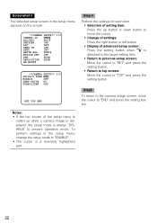
... END SETUP DISABLE Screenshot 2 The setup mode changes to "ENABLE", and the setup menu becomes ready to be set . MODEL WV-CL930 SERIES CAMERA BACK-FOCUS SPECIAL LANGUAGE END SETUP ENABLE 21 The operations in the setup menu are performed with the operation buttons ( page 9) after calling up ... the system controller (option). The operations in the setup menu can also be set , and press the setting button. MODEL WV-CL930 SERIES CAMERA BACK-FOCUS SPECIAL LANGUAGE Step 1 Press the up button or the down the setting button for approx. 2 seconds to operate the setup menu ...
... END SETUP DISABLE Screenshot 2 The setup mode changes to "ENABLE", and the setup menu becomes ready to be set . MODEL WV-CL930 SERIES CAMERA BACK-FOCUS SPECIAL LANGUAGE END SETUP ENABLE 21 The operations in the setup menu are performed with the operation buttons ( page 9) after calling up ... the system controller (option). The operations in the setup menu can also be set , and press the setting button. MODEL WV-CL930 SERIES CAMERA BACK-FOCUS SPECIAL LANGUAGE Step 1 Press the up button or the down the setting button for approx. 2 seconds to operate the setup menu ...
WVCL930 User Guide
Page 22
... OFF ALC/ELC ALC SHUTTER OFF AGC ON SENS UP OFF SYNC INT WHITE BAL ATW1 MOTION DET OFF DNR HIGH RESOLUTION HIGH BW MODE **CAMERA SETUP** 2/2 PRIVACY ZONE OFF MIRROR OFF LENS-DRIVE DC STABILIZER OFF RET TOP END Step 4 Perform the settings for each item. • Selection... of setting item: Press the up while a camera image is displayed, the setup mode is always "DISABLE" to prevent operation errors. Screenshot 3 The selected setup screen in the setup menu, change the ...
... OFF ALC/ELC ALC SHUTTER OFF AGC ON SENS UP OFF SYNC INT WHITE BAL ATW1 MOTION DET OFF DNR HIGH RESOLUTION HIGH BW MODE **CAMERA SETUP** 2/2 PRIVACY ZONE OFF MIRROR OFF LENS-DRIVE DC STABILIZER OFF RET TOP END Step 4 Perform the settings for each item. • Selection... of setting item: Press the up while a camera image is displayed, the setup mode is always "DISABLE" to prevent operation errors. Screenshot 3 The selected setup screen in the setup menu, change the ...
WVCL930 User Guide
Page 23
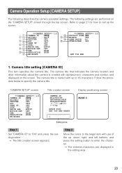
...END RESET Editing area Display positioning screen FLOOR 1 Step 1 Set "CAMERA ID" to specify the camera title. Camera Operation Setup [CAMERA SETUP] The following settings are displayed in the editing area. 23 q w e r t y u i o !0 !1 **CAMERA SETUP** 1/2 CAMERA ID OFF ALC/ELC ALC SHUTTER OFF AGC ON SENS UP OFF... SYNC INT WHITE BAL ATW1 MOTION DET OFF DNR HIGH RESOLUTION HIGH BW MODE !2 !3 !4 !5 **CAMERA SETUP** 2/2 PRIVACY ZONE OFF MIRROR OFF LENS-DRIVE DC STABILIZER OFF RET TOP END 1. Step 2 Move the cursor to enter the ...
...END RESET Editing area Display positioning screen FLOOR 1 Step 1 Set "CAMERA ID" to specify the camera title. Camera Operation Setup [CAMERA SETUP] The following settings are displayed in the editing area. 23 q w e r t y u i o !0 !1 **CAMERA SETUP** 1/2 CAMERA ID OFF ALC/ELC ALC SHUTTER OFF AGC ON SENS UP OFF... SYNC INT WHITE BAL ATW1 MOTION DET OFF DNR HIGH RESOLUTION HIGH BW MODE !2 !3 !4 !5 **CAMERA SETUP** 2/2 PRIVACY ZONE OFF MIRROR OFF LENS-DRIVE DC STABILIZER OFF RET TOP END 1. Step 2 Move the cursor to enter the ...
WVCL930 User Guide
Page 24
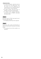
... the character to be revised with use of the right and left buttons to decide the title position and press the setting button. → The camera title and title position are specified. 24 Step 4 Use the up, down, right, and left buttons, and enter a correct character. • To enter a blank, move...
... the character to be revised with use of the right and left buttons to decide the title position and press the setting button. → The camera title and title position are specified. 24 Step 4 Use the up, down, right, and left buttons, and enter a correct character. • To enter a blank, move...
WVCL930 User Guide
Page 25
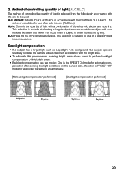
...areas. • Backlight compensation has two modes: One is the PRESET ON mode for automatic compensation after sensing the light conditions on the camera side, the other is suitable for use of light is suitable for specifying the sensing area manually. [No backlight compensation performed] [Backlight ...may occur when a subject is suitable at shooting a bright subject such as a spotlight in its background, the subject appears shadowy because the camera adjusts the iris in accordance with the lens to be used. This selection is PRESET OFF mode for use of a lens with a combination...
...areas. • Backlight compensation has two modes: One is the PRESET ON mode for automatic compensation after sensing the light conditions on the camera side, the other is suitable for use of light is suitable for specifying the sensing area manually. [No backlight compensation performed] [Backlight ...may occur when a subject is suitable at shooting a bright subject such as a spotlight in its background, the subject appears shadowy because the camera adjusts the iris in accordance with the lens to be used. This selection is PRESET OFF mode for use of a lens with a combination...
WVCL930 User Guide
Page 26
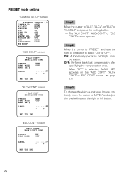
... after specifying the compensation area. Step 2 Move the cursor to "PRESET" and use the right or left button. 26 pensation. PRESET mode setting "CAMERA SETUP" screen **CAMERA SETUP** 1/2 CAMERA ID OFF ALC/ELC ALC SHUTTER OFF AGC ON SENS UP OFF SYNC INT WHITE BAL ATW1 MOTION DET OFF DNR HIGH RESOLUTION HIGH...
... after specifying the compensation area. Step 2 Move the cursor to "PRESET" and use the right or left button. 26 pensation. PRESET mode setting "CAMERA SETUP" screen **CAMERA SETUP** 1/2 CAMERA ID OFF ALC/ELC ALC SHUTTER OFF AGC ON SENS UP OFF SYNC INT WHITE BAL ATW1 MOTION DET OFF DNR HIGH RESOLUTION HIGH...


