Owner's Manual
Page 179
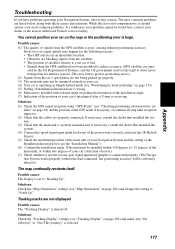
... are properly connected. Tracking marks are not displayed. Solutions: (1) Check the GPS signal reception using "GPS Status" (see the "Installation Manual"). (6) Confirm the installation angle. (This unit must be mounted securely in your car. (4) Your car is operating in an unsuitable location.... Solutions: Check the "Map Orientation" settings (see "Tracking Display" on page 173). (5) Setting of your dealer or the nearest authorized Pioneer service facility. You cannot position your car is misaligned after a U-turn or reversing. Such a loss of signal quality may not be...
... are properly connected. Tracking marks are not displayed. Solutions: (1) Check the GPS signal reception using "GPS Status" (see the "Installation Manual"). (6) Confirm the installation angle. (This unit must be mounted securely in your car. (4) Your car is operating in an unsuitable location.... Solutions: Check the "Map Orientation" settings (see "Tracking Display" on page 173). (5) Setting of your dealer or the nearest authorized Pioneer service facility. You cannot position your car is misaligned after a U-turn or reversing. Such a loss of signal quality may not be...

Other Manual
Page 3
... using the adhesive tape 15 Installing the main unit 16 - CAUTION After installing the unit 30 FRANÇAIS ITALIANO NEDERLANDS 2 DIN Rear-mount: Installation using tapping screws - Parts supplied - Installation notes - When installing the microphone on the body) Installing the Remote controller 25 -... Connecting to the display with the left and right sides of the unit Installing the GPS antenna 22 - When installing the microphone on the floor under a seat, etc., using the screw holes on the dashboard or rear shelf...
... using the adhesive tape 15 Installing the main unit 16 - CAUTION After installing the unit 30 FRANÇAIS ITALIANO NEDERLANDS 2 DIN Rear-mount: Installation using tapping screws - Parts supplied - Installation notes - When installing the microphone on the body) Installing the Remote controller 25 -... Connecting to the display with the left and right sides of the unit Installing the GPS antenna 22 - When installing the microphone on the floor under a seat, etc., using the screw holes on the dashboard or rear shelf...

Other Manual
Page 18
Installation Parts supplied Main unit Binding screw (5 × 6 mm) (4 pcs.) Flush surface screw (5 × 6 mm) (4 pcs.) Tapping screw (6 × 16 mm) (4 pcs.) Mounting angle (2 pcs.) 17
Installation Parts supplied Main unit Binding screw (5 × 6 mm) (4 pcs.) Flush surface screw (5 × 6 mm) (4 pcs.) Tapping screw (6 × 16 mm) (4 pcs.) Mounting angle (2 pcs.) 17

Other Manual
Page 19
...direction of travel, switch the installation direction lever, and attach the locking screw to the "↔" side, or else the G sensor mounted in the DVD Navigation Unit will be displayed incorrectly. • If you install with the left and right sides of the DVD Navigation ...Unit parallel to your car's forward / backward direction, remove the mounting screw underneath the DVD Navigation Unit, and switch the installation direction lever. Switch the lever, and attach the mounting screw to "↕" side. Remove the locking screw attached to your car's direction...
...direction of travel, switch the installation direction lever, and attach the locking screw to the "↔" side, or else the G sensor mounted in the DVD Navigation Unit will be displayed incorrectly. • If you install with the left and right sides of the DVD Navigation ...Unit parallel to your car's forward / backward direction, remove the mounting screw underneath the DVD Navigation Unit, and switch the installation direction lever. Switch the lever, and attach the mounting screw to "↕" side. Remove the locking screw attached to your car's direction...

Other Manual
Page 20
Mounting angle Binding screw or flush surface screw 19 Use the following holes on the floor under a seat, etc., using tapping screws 1. Installation When installing the main unit inside the trunk, on the mounting angles. Fit mounting angles to the sides of the main unit.
Mounting angle Binding screw or flush surface screw 19 Use the following holes on the floor under a seat, etc., using tapping screws 1. Installation When installing the main unit inside the trunk, on the mounting angles. Fit mounting angles to the sides of the main unit.

Other Manual
Page 21
CAUTION • Before drilling any mounting holes, confirm that the screws will not interfere with tapping screws. ENGLISH ESPAÑOL 2. Fix to 4.5 mm diameter holes. DEUTSCH FRANÇAIS ITALIANO NEDERLANDS 20 Tapping screw Floor Drill 4 to the floor with any of the car's operating systems (such as the fuel line, brake lines, electrical wiring, etc.).
CAUTION • Before drilling any mounting holes, confirm that the screws will not interfere with tapping screws. ENGLISH ESPAÑOL 2. Fix to 4.5 mm diameter holes. DEUTSCH FRANÇAIS ITALIANO NEDERLANDS 20 Tapping screw Floor Drill 4 to the floor with any of the car's operating systems (such as the fuel line, brake lines, electrical wiring, etc.).

Other Manual
Page 22
Installation DIN Rear-mount: Installation using the screw holes on each side. Select a position where the screw holes of the bracket and the screw holes of the head unit become aligned (are fitted), and tighten the screws at 2 places on the side of the screw holes in the bracket. Mounting bracket Screw Dashboard or Console 21 Use either binding screws (5 × 6 mm) or flush surface screws (5 × 6 mm), depending on the shape of the unit • Fastening the unit to the factory radio mounting bracket.
Installation DIN Rear-mount: Installation using the screw holes on each side. Select a position where the screw holes of the bracket and the screw holes of the head unit become aligned (are fitted), and tighten the screws at 2 places on the side of the screw holes in the bracket. Mounting bracket Screw Dashboard or Console 21 Use either binding screws (5 × 6 mm) or flush surface screws (5 × 6 mm), depending on the shape of the unit • Fastening the unit to the factory radio mounting bracket.