Service Manual
Page 1
... 1-Chome, Meguro-ku, Tokyo 153-8654, Japan PIONEER ELECTRONICS SERVICE INC. ADJUSTMENT 45 7. The CD mechanism employed in Japan EXPLODED VIEWS AND PARTS LIST 2 3. P.O.Box 1760, Long Beach, CA 90801-1760 U.S.A. PCB CONNECTION DIAGRAM 28 5. GENERAL INFORMATION 49 7.1 PARTS 49 7.1.1 ... 7.2.1 DISASSEMBLY 57 7.2.2 TEST MODE 58 7.3 BLOCK DIAGRAM 62 8. SCHEMATIC DIAGRAM 12 4. See the separate manual CX-916(CRT2300) for the CD mechanism description, disassembly and circuit description. - PIONEER ELECTRONIC [EUROPE] N.V. Service DEH-P2000/X1N/UC Manual MULTI-CD CONTROL HIGH POWER CD ...
... 1-Chome, Meguro-ku, Tokyo 153-8654, Japan PIONEER ELECTRONICS SERVICE INC. ADJUSTMENT 45 7. The CD mechanism employed in Japan EXPLODED VIEWS AND PARTS LIST 2 3. P.O.Box 1760, Long Beach, CA 90801-1760 U.S.A. PCB CONNECTION DIAGRAM 28 5. GENERAL INFORMATION 49 7.1 PARTS 49 7.1.1 ... 7.2.1 DISASSEMBLY 57 7.2.2 TEST MODE 58 7.3 BLOCK DIAGRAM 62 8. SCHEMATIC DIAGRAM 12 4. See the separate manual CX-916(CRT2300) for the CD mechanism description, disassembly and circuit description. - PIONEER ELECTRONIC [EUROPE] N.V. Service DEH-P2000/X1N/UC Manual MULTI-CD CONTROL HIGH POWER CD ...

Service Manual
Page 12
1 2 3 4 DEH-P2000,P20,P2050 3. SCHEMATIC DIAGRAM 3.1 OVERALL CONNECTION DIAGRAM(GUIDE PAGE) A Note: When ordering service parts, be sure to refer to "EXPLODED VIEWS AND PARTS LIST" or "ELECTRICAL PARTS LIST". Large size A-a A-b SCH diagram A A A-a IP BUS IN 4.3V 4.3V 4.3V 4.3V A-a A-b Guide page B A-a A-b Detailed page IP BUS DRIVER 4.3V 4.3V 4.3V SO ELE 4.3V B DE C ANTENNA CABLE D A 12 1 2 3 VD REGULATOR 4
1 2 3 4 DEH-P2000,P20,P2050 3. SCHEMATIC DIAGRAM 3.1 OVERALL CONNECTION DIAGRAM(GUIDE PAGE) A Note: When ordering service parts, be sure to refer to "EXPLODED VIEWS AND PARTS LIST" or "ELECTRICAL PARTS LIST". Large size A-a A-b SCH diagram A A A-a IP BUS IN 4.3V 4.3V 4.3V 4.3V A-a A-b Guide page B A-a A-b Detailed page IP BUS DRIVER 4.3V 4.3V 4.3V SO ELE 4.3V B DE C ANTENNA CABLE D A 12 1 2 3 VD REGULATOR 4
Service Manual
Page 24
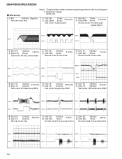
...; REFO → REFO → 3 CH1: FD 4 CH2: FO+ 0.5V/div. 0.2s/div. 2V/div. The encircled numbers denote measuring pointes in the circuit diagram. 2. Normal mode: Play Normal mode: Focus close (12cm) Normal mode: Focus close 6 CH1: FE 7 CH2: XSI 0.5V/div. 1ms/div. 2V/div. Normal...→ 24 REFO → REFO → REFO → REFO → Normal mode: play 1 CH1: RFI 2 CH2: MIRR 1V/div. 0.5ms/div. 5V/div. DEH-P2000,P20,P2050 - Waveforms Note:1. Test mode: Tracking open 1 CH1: RFI 1V/div. 2 CH2: MIRR 5V/div. 0.5ms/div. Normal mode: Focus close 3 CH1: FD...
...; REFO → REFO → 3 CH1: FD 4 CH2: FO+ 0.5V/div. 0.2s/div. 2V/div. The encircled numbers denote measuring pointes in the circuit diagram. 2. Normal mode: Play Normal mode: Focus close (12cm) Normal mode: Focus close 6 CH1: FE 7 CH2: XSI 0.5V/div. 1ms/div. 2V/div. Normal...→ 24 REFO → REFO → REFO → REFO → Normal mode: play 1 CH1: RFI 2 CH2: MIRR 1V/div. 0.5ms/div. 5V/div. DEH-P2000,P20,P2050 - Waveforms Note:1. Test mode: Tracking open 1 CH1: RFI 1V/div. 2 CH2: MIRR 5V/div. 0.5ms/div. Normal mode: Focus close 3 CH1: FD...

Service Manual
Page 28
For further information for several destination. 1 2 3 4 DEH-P2000,P20,P2050 4. gram. 2. The parts mounted on this PCB A TUNER AMP UNIT include all necessary parts for respective destinations, be sure to check with the schematic dia- PCB CONNECTION DIAGRAM 4.1 TUNER AMP UNIT A NOTE FOR PCB DIAGRAMS 1. Viewpoint of PCB diagrams CORD ASSY Connector Capacitor SIDE A B P.C.Board Chip Part SIDE B C D CN701 D A 28 1 2 3 4
For further information for several destination. 1 2 3 4 DEH-P2000,P20,P2050 4. gram. 2. The parts mounted on this PCB A TUNER AMP UNIT include all necessary parts for respective destinations, be sure to check with the schematic dia- PCB CONNECTION DIAGRAM 4.1 TUNER AMP UNIT A NOTE FOR PCB DIAGRAMS 1. Viewpoint of PCB diagrams CORD ASSY Connector Capacitor SIDE A B P.C.Board Chip Part SIDE B C D CN701 D A 28 1 2 3 4

Service Manual
Page 47
...press. 4. As shown in the CD mechanism module is thus the best adjusted PU unit for the CD mechanism module. The PU unit in the diagram above indicates the average angle. • Hint Reloading the disc changes the clamp position and may decrease the "wobble". 47 However, if the PU...that the phase difference is off by a large amount symptoms such as being unable to see if there is changed , the grating should read "81". DEH-P2000,P20,P2050 6.2 CHECKING THE GRATING AFTER CHANGING THE PICKUP UNIT • Note : The grating angle of the PU unit cannot be adjusted after trying ...
...press. 4. As shown in the CD mechanism module is thus the best adjusted PU unit for the CD mechanism module. The PU unit in the diagram above indicates the average angle. • Hint Reloading the disc changes the clamp position and may decrease the "wobble". 47 However, if the PU...that the phase difference is off by a large amount symptoms such as being unable to see if there is changed , the grating should read "81". DEH-P2000,P20,P2050 6.2 CHECKING THE GRATING AFTER CHANGING THE PICKUP UNIT • Note : The grating angle of the PU unit cannot be adjusted after trying ...


