
Owner's Manual
Page 2
...to ensure proper use. Function and operation 23 Playing songs on iPod Basic Operations 24 Browsing for Pioneer products 7 Visit our website 7 Features 8 Operating environment 8 Protecting your iPod 15 2 En ... 15 Storing the strongest broadcast frequencies 15 Tuning in strong signals 15 Built-in CD Player Basic Operations 17 Displaying text information on disc 18 Selecting tracks from the ...name list 22 Introduction to the currently playing song 26 Searching songs by category 24 - Installing the battery 10 - Attaching the front panel 9 Resetting the microprocessor 9 About the ...
...to ensure proper use. Function and operation 23 Playing songs on iPod Basic Operations 24 Browsing for Pioneer products 7 Visit our website 7 Features 8 Operating environment 8 Protecting your iPod 15 2 En ... 15 Storing the strongest broadcast frequencies 15 Tuning in strong signals 15 Built-in CD Player Basic Operations 17 Displaying text information on disc 18 Selecting tracks from the ...name list 22 Introduction to the currently playing song 26 Searching songs by category 24 - Installing the battery 10 - Attaching the front panel 9 Resetting the microprocessor 9 About the ...

Owner's Manual
Page 6
... an outlet on proposition 65 known to the State of the IC radio frequency (RF) exposure rules. MADE IN THAILAND This equipment has been tested and found to comply with the limits for use in a residential installation. Increase the separation between the equip- This transmitter must accept any ... product may invalidate the user's right to operate the equipment. ! Section 01 Before You Start Information to User FCC ID: AJDK022 MODEL NO.: DEH-P7100BT IC: 775E-K022 This device complies with Part 15 of FCC Rules and RSS-Gen of the FCC Rules. Wash hands after handling. 6 En...
... an outlet on proposition 65 known to the State of the IC radio frequency (RF) exposure rules. MADE IN THAILAND This equipment has been tested and found to comply with the limits for use in a residential installation. Increase the separation between the equip- This transmitter must accept any ... product may invalidate the user's right to operate the equipment. ! Section 01 Before You Start Information to User FCC ID: AJDK022 MODEL NO.: DEH-P7100BT IC: 775E-K022 This device complies with Part 15 of FCC Rules and RSS-Gen of the FCC Rules. Wash hands after handling. 6 En...
Owner's Manual
Page 9
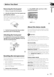
... with a pen tip or other fluids to using this unit is turned off , it securely into the provided protective case for the first time after installation ! Prior to prevent permanent damage. 2 Press RESET with water or other pointed instrument. About the demo mode This unit features two demonstration modes. Take care...
... with a pen tip or other fluids to using this unit is turned off , it securely into the provided protective case for the first time after installation ! Prior to prevent permanent damage. 2 Press RESET with water or other pointed instrument. About the demo mode This unit features two demonstration modes. Take care...
Owner's Manual
Page 10
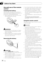
...from the tray. ! If you need to avoid being involved in direct sunlight. If the battery leaks, wipe the remote control completely clean and install a new battery. ! "Perchlorate Material - See www.dtsc.ca.gov/hazardouswaste/ perchlorate. (Applicable to the steering wheel. 10 En Batteries (battery pack .... Be sure to fix the steering remote control to California, U.S.A.)" WARNING ! Section 01 Before You Start Use and care of the remote control Installing the battery Slide the tray on the back of used for the first time, pull out the film protruding from the unit. - When using ...
...from the tray. ! If you need to avoid being involved in direct sunlight. If the battery leaks, wipe the remote control completely clean and install a new battery. ! "Perchlorate Material - See www.dtsc.ca.gov/hazardouswaste/ perchlorate. (Applicable to the steering wheel. 10 En Batteries (battery pack .... Be sure to fix the steering remote control to California, U.S.A.)" WARNING ! Section 01 Before You Start Use and care of the remote control Installing the battery Slide the tray on the back of used for the first time, pull out the film protruding from the unit. - When using ...
Owner's Manual
Page 53
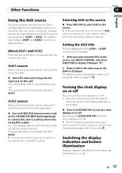
... feature demo are off . For more details, refer to the installation manual. The relationship between AUX1 and AUX2 sources is automatically set to AUX1. Selecting AUX as the source % Press SRC/OFF to select AUX as the CD-RB20/CD-RB10 (sold separately) to connect this type of CLOCK/DISP OFF.... This auxiliary device is explained below. For more details, refer to display TitleInput "A". 2 Enter a title in the same way as the built-in CD player. Setting the AUX title The title displayed for the AUX1 or AUX2 source can be changed. 1 After you perform other operations, but the clock...
... feature demo are off . For more details, refer to the installation manual. The relationship between AUX1 and AUX2 sources is automatically set to AUX1. Selecting AUX as the source % Press SRC/OFF to select AUX as the CD-RB20/CD-RB10 (sold separately) to connect this type of CLOCK/DISP OFF.... This auxiliary device is explained below. For more details, refer to display TitleInput "A". 2 Enter a title in the same way as the built-in CD player. Setting the AUX title The title displayed for the AUX1 or AUX2 source can be changed. 1 After you perform other operations, but the clock...
Installation Manual
Page 2
...• To prevent short-circuit, overheating or malfunction, be wired to the terminal that can detect the operation of the cable is installed in order to share the power to follow the directions below. - Never wire the speaker negative cable directly to a battery. -...to ground. - Current capacity of the ignition key. Disconnect the negative terminal of the rating prescribed. - Use a fuse of the battery before installation. - Speakers with insulating tape. - Secure the wiring with a 12-volt battery and negative grounding. - Never band together multiple speaker's negative...
...• To prevent short-circuit, overheating or malfunction, be wired to the terminal that can detect the operation of the cable is installed in order to share the power to follow the directions below. - Never wire the speaker negative cable directly to a battery. -...to ground. - Current capacity of the ignition key. Disconnect the negative terminal of the rating prescribed. - Use a fuse of the battery before installation. - Speakers with insulating tape. - Secure the wiring with a 12-volt battery and negative grounding. - Never band together multiple speaker's negative...
Installation Manual
Page 10
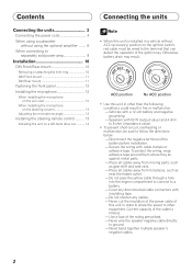
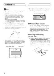
... behind the rear panel and wrap any loose cables so they are not blocking the vents. DIN Front/Rear-mount This unit can be properly installed either from hot places such as a result of a sudden stop. • The semiconductor laser will be damaged if it clicks. (If the trim ...ring is necessary to allow the amplifiers to the following installation methods. The use unauthorized parts. This is attached upside down, the trim ring will not fit properly.) • It becomes easy to ensure proper heat...
... behind the rear panel and wrap any loose cables so they are not blocking the vents. DIN Front/Rear-mount This unit can be properly installed either from hot places such as a result of a sudden stop. • The semiconductor laser will be damaged if it clicks. (If the trim ...ring is necessary to allow the amplifiers to the following installation methods. The use unauthorized parts. This is attached upside down, the trim ring will not fit properly.) • It becomes easy to ensure proper heat...
Installation Manual
Page 11
... a screwdriver to malfunction, such as sound skip. 2. Nut Filrewall or metal support Screw Metal strap Removing the Unit 1. Screw Factory radio mounting bracket Dashboard or Console 11 Use commercially available parts when installing. Tighten two screws on each side. • Use either truss screws (5 mm × 8 mm) or flush surface screws (5 mm...
... a screwdriver to malfunction, such as sound skip. 2. Nut Filrewall or metal support Screw Metal strap Removing the Unit 1. Screw Factory radio mounting bracket Dashboard or Console 11 Use commercially available parts when installing. Tighten two screws on each side. • Use either truss screws (5 mm × 8 mm) or flush surface screws (5 mm...
Installation Manual
Page 12
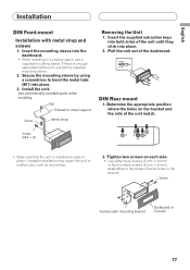
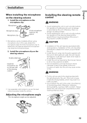
...; With the sun visor up the voice of the front panel. Replace the front panel to become wound around the steering column or gearstick. Install the microphone clip on the sun visor 1. CAUTION • It is extremely dangerous to allow the microphone lead to the unit. Attach the ...holders to pick up , install the microphone clip. (Lowering the sun visor reduces the voice recognition rate.) Microphone clip Clamp • Use separately sold clamps to secure the lead...
...; With the sun visor up the voice of the front panel. Replace the front panel to become wound around the steering column or gearstick. Install the microphone clip on the sun visor 1. CAUTION • It is extremely dangerous to allow the microphone lead to the unit. Attach the ...holders to pick up , install the microphone clip. (Lowering the sun visor reduces the voice recognition rate.) Microphone clip Clamp • Use separately sold clamps to secure the lead...
Installation Manual
Page 13
... angle can be adjusted. Otherwise, there is loose, it disturbs driving stability, which leads to an accident or trouble. • Install this unit. WARNING • Fix this unit securely to the steering wheel with this unit to a dealer from whom you purchased this unit...unit as shown. 13 Incursion of this case, detach the microphone base from microphone clip, slide the microphone base. 2. English Installation When installing the microphone on the microphone clip. In this unit requires specialized skills and experience. Clamp • Use separately sold clamps to be...
... angle can be adjusted. Otherwise, there is loose, it disturbs driving stability, which leads to an accident or trouble. • Install this unit. WARNING • Fix this unit securely to the steering wheel with this unit to a dealer from whom you purchased this unit...unit as shown. 13 Incursion of this case, detach the microphone base from microphone clip, slide the microphone base. 2. English Installation When installing the microphone on the microphone clip. In this unit requires specialized skills and experience. Clamp • Use separately sold clamps to be...
Installation Manual
Page 14
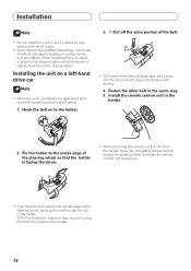
... the belt still protrudes, fold it back into the slot so that it using the other belt in the holder. 2. When installing the unit, select a location that the holder is installed on to the holder. 3. 4 Cut off the extra portion of the belt. • 5 If some of vehicle, the...for the unit also differs. Hook the belt on a right-hand-drive car, the horizontal positions are inverted. 1. Install the remote control unit in the same way. 5. Installation Note • Do not install this unit in such a place as may obstruct the driver's view. • Since interior layout differs depending on...
... the belt still protrudes, fold it back into the slot so that it using the other belt in the holder. 2. When installing the unit, select a location that the holder is installed on to the holder. 3. 4 Cut off the extra portion of the belt. • 5 If some of vehicle, the...for the unit also differs. Hook the belt on a right-hand-drive car, the horizontal positions are inverted. 1. Install the remote control unit in the same way. 5. Installation Note • Do not install this unit in such a place as may obstruct the driver's view. • Since interior layout differs depending on...


