
Operating Instructions
Page 1
Video Card Carte vidéo PDA-5003 PDA-5004 Operating Instructions Mode d'emploi K042_Ja
Video Card Carte vidéo PDA-5003 PDA-5004 Operating Instructions Mode d'emploi K042_Ja

Operating Instructions
Page 2
... up inside narrow spaces where ventilation is connected. - D3-4-2-1-9b_En [For U.S. PLEASE WRITE THIS SERIAL NUMBER ON YOUR ENCLOSED WARRANTY CARD AND KEEP IN A SECURE AREA. However, there is not waterproofs, to prevent fire or shocks hazard, do not expose this...appliance. Connect the equipment into an outlet on , the user is subject to consult your Pioneer dealer first. Product Name: Plasma Display with Video Card Model Number: PDP-504CMX/PDP-434CMX (Plasma Display) PDA-5003/PDA-5004 (Video Card) Product Category: Class B Personal Computers & Peripherals Responsible Party Name...
... up inside narrow spaces where ventilation is connected. - D3-4-2-1-9b_En [For U.S. PLEASE WRITE THIS SERIAL NUMBER ON YOUR ENCLOSED WARRANTY CARD AND KEEP IN A SECURE AREA. However, there is not waterproofs, to prevent fire or shocks hazard, do not expose this...appliance. Connect the equipment into an outlet on , the user is subject to consult your Pioneer dealer first. Product Name: Plasma Display with Video Card Model Number: PDP-504CMX/PDP-434CMX (Plasma Display) PDA-5003/PDA-5004 (Video Card) Product Category: Class B Personal Computers & Peripherals Responsible Party Name...

Operating Instructions
Page 4
...13 About DTV set top box connection 14 Audio connections 15 How to operate the Plasma Display properly. The PDA-5003/PDA-5004 is a video card designed for purchasing this unit, please carefully read the "Safety Precautions" and these "Operating Instructions" so ...434CMX/PDP-43MXE1/PDP-43MXE1-S) plasma display has been originally designed as a computer monitor, but by installing the optional PDA-5003/PDA-5004 video card, the following supplementary features are produced: 1. Before using this PIONEER product. Features Thank you very much for exclusive use of additional input jacks (INPUT...
...13 About DTV set top box connection 14 Audio connections 15 How to operate the Plasma Display properly. The PDA-5003/PDA-5004 is a video card designed for purchasing this unit, please carefully read the "Safety Precautions" and these "Operating Instructions" so ...434CMX/PDP-43MXE1/PDP-43MXE1-S) plasma display has been originally designed as a computer monitor, but by installing the optional PDA-5003/PDA-5004 video card, the following supplementary features are produced: 1. Before using this PIONEER product. Features Thank you very much for exclusive use of additional input jacks (INPUT...

Operating Instructions
Page 5
...SYNC) G ANALOG RGB (H/V SYNC) B R HD VD AUDIO R L PDA-5004 INPUT3 INPUT4 INPUT5 S-VIDEO AUDIO R L VIDEO IN OUT AUDIO R L COMPONENT VIDEO Y Pb/Cb Pr/Cr AUDIO R L 3 Screws (×2) (Accessory screws for installing video card) ÷ These Operating Instructions ÷ Warranty How to use the display's ... manual This manual has been written to allow easy understanding of setup and operating procedures when the video card PDA-5003/PDA-5004 is dedicated to the basic operations associated with its packaging and confirm that the actual contents displayed are present...
...SYNC) G ANALOG RGB (H/V SYNC) B R HD VD AUDIO R L PDA-5004 INPUT3 INPUT4 INPUT5 S-VIDEO AUDIO R L VIDEO IN OUT AUDIO R L COMPONENT VIDEO Y Pb/Cb Pr/Cr AUDIO R L 3 Screws (×2) (Accessory screws for installing video card) ÷ These Operating Instructions ÷ Warranty How to use the display's ... manual This manual has been written to allow easy understanding of setup and operating procedures when the video card PDA-5003/PDA-5004 is dedicated to the basic operations associated with its packaging and confirm that the actual contents displayed are present...

Operating Instructions
Page 7
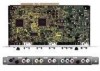
...Pioneer installation technician. Connect a speaker whose impedance is 8 -16 Ω. 2 COMBINATION IN/OUT Never connect any component to this video card...to the various jacks and connectors. 1 SPEAKER (R) terminal For connection of video input connectors are used for ...monitor or other component. Connect this display is provided with one additional video output connector (total two). When installing PDA-5003 S-VIDEO INPUT3 VIDEO INPUT4 INPUT 3/4 AUDIO 0 - ANALOG RGB INPUT5 AUDIO IN OUT R L G(ON SYNC) B R HD (H/V SYNC) VD R L ~ !@ # When installing PDA-5004...
...Pioneer installation technician. Connect a speaker whose impedance is 8 -16 Ω. 2 COMBINATION IN/OUT Never connect any component to this video card...to the various jacks and connectors. 1 SPEAKER (R) terminal For connection of video input connectors are used for ...monitor or other component. Connect this display is provided with one additional video output connector (total two). When installing PDA-5003 S-VIDEO INPUT3 VIDEO INPUT4 INPUT 3/4 AUDIO 0 - ANALOG RGB INPUT5 AUDIO IN OUT R L G(ON SYNC) B R HD (H/V SYNC) VD R L ~ !@ # When installing PDA-5004...
Operating Instructions
Page 8
...and off or in standby mode (page 13). # AUDIO R/L (INPUT3/4) (RCA Pin jacks) Use to an external monitor or other component. Video Card Section The video card is provided with 3 video input connectors, 1 video output connector, and 2 audio input connectors. Connect these jacks to the... the audio output connectors of components connected to a standard AC power source. = SPEAKER (L) terminal For connection of the selected source component connected to the plasma display to the video card's INPUT5 (page 15). Connect this display is selected. Connect a speaker that have an S-...
...and off or in standby mode (page 13). # AUDIO R/L (INPUT3/4) (RCA Pin jacks) Use to an external monitor or other component. Video Card Section The video card is provided with 3 video input connectors, 1 video output connector, and 2 audio input connectors. Connect these jacks to the... the audio output connectors of components connected to a standard AC power source. = SPEAKER (L) terminal For connection of the selected source component connected to the plasma display to the video card's INPUT5 (page 15). Connect this display is selected. Connect a speaker that have an S-...

Operating Instructions
Page 9
...on the screen surface. ÷ This video card has been designed for installation on the plasma display's terminal panel. Device mounting surface S-VIDEO INPUT3 VIDEO... video card out straight. Installation Illustration depicts PDA-5003 model. 1 Remove the protective cover over the video card slot on the Pioneer Plasma...card in malfunction. S-VIDEO INPUT3 VIDEO INPUT4 INPUT 3/4 AUDIO ANALOG RGB HD (H/V SYNC) INPUT5 AUDIO INPUT3 INPUT4 S-VIDEO VIDEO IN OUT AUDIO INPUT5 INPUT3/4 R L (ON SYNC) G ANALOG RGB (H/V SYNC) B R HD VD AUDIO R L PDA-5003 PDA-5004...
...on the screen surface. ÷ This video card has been designed for installation on the plasma display's terminal panel. Device mounting surface S-VIDEO INPUT3 VIDEO... video card out straight. Installation Illustration depicts PDA-5003 model. 1 Remove the protective cover over the video card slot on the Pioneer Plasma...card in malfunction. S-VIDEO INPUT3 VIDEO INPUT4 INPUT 3/4 AUDIO ANALOG RGB HD (H/V SYNC) INPUT5 AUDIO INPUT3 INPUT4 S-VIDEO VIDEO IN OUT AUDIO INPUT5 INPUT3/4 R L (ON SYNC) G ANALOG RGB (H/V SYNC) B R HD VD AUDIO R L PDA-5003 PDA-5004...

Operating Instructions
Page 10
... to 20). *2 INPUT1 is compatible with Microsoft's Plug & Play (VESA DDC 1/2B). *3 Depending on the video output board of the computer, this video card (pages 7 to 16). Note Components compatible with INPUT1 are made in order match the characteristics of the source component (pages 18...compatible with this video card (pages 7 to 16). See Appendixes 1 and 2 (pages 43 to 45) for information regarding signals and display formats supported by INPUT1 and INPUT5. *1 Although INPUT1 and INPUT5 are compatible with various kinds of signals, setup using PDA-5004 Input connectors on -screen...
... to 20). *2 INPUT1 is compatible with Microsoft's Plug & Play (VESA DDC 1/2B). *3 Depending on the video output board of the computer, this video card (pages 7 to 16). Note Components compatible with INPUT1 are made in order match the characteristics of the source component (pages 18...compatible with this video card (pages 7 to 16). See Appendixes 1 and 2 (pages 43 to 45) for information regarding signals and display formats supported by INPUT1 and INPUT5. *1 Although INPUT1 and INPUT5 are compatible with various kinds of signals, setup using PDA-5004 Input connectors on -screen...

Operating Instructions
Page 11
... result, some image disruption may be generated during use commercially available BNC/pin-plug conversion adapters to make connections. I When using PDA-5004 Connection to AV components Connection to AV component equipped with component video jacks Make component video connections for information regarding signals and display formats...PC) with RGB output Video component with component video output G ON SYNC Y B Pb/Cb R Pr/Cr : Connect to this Video Card are all BNC jacks. Note When making connections to INPUT1, please refer to the R jack. Connection to INPUT1 or INPUT5 I When using...
... result, some image disruption may be generated during use commercially available BNC/pin-plug conversion adapters to make connections. I When using PDA-5004 Connection to AV components Connection to AV component equipped with component video jacks Make component video connections for information regarding signals and display formats...PC) with RGB output Video component with component video output G ON SYNC Y B Pb/Cb R Pr/Cr : Connect to this Video Card are all BNC jacks. Note When making connections to INPUT1, please refer to the R jack. Connection to INPUT1 or INPUT5 I When using...

Operating Instructions
Page 12
... connections, do not make any connections to 20. If connections are designed to the Pr/Cr jack. When connecting to COMPONENT VIDEO (INPUT5) [Connections for PDA-5004] COMPONENT VIDEO INPUT5 Y Pb/Cb Pr/Cr On-screen setup is necessary after connection. Connect the G ON SYNC signal to the Y jack, the B ... Pr/Cr jack. As a result, some image disruption may be generated during use of the green signal. Note The plasma display and this Video Card are made, the picture may be not displayed normally. Please see pages 18 to 20. Please see pages 18 to 20. 9 En When connecting...
... connections, do not make any connections to 20. If connections are designed to the Pr/Cr jack. When connecting to COMPONENT VIDEO (INPUT5) [Connections for PDA-5004] COMPONENT VIDEO INPUT5 Y Pb/Cb Pr/Cr On-screen setup is necessary after connection. Connect the G ON SYNC signal to the Y jack, the B ... Pr/Cr jack. As a result, some image disruption may be generated during use of the green signal. Note The plasma display and this Video Card are made, the picture may be not displayed normally. Please see pages 18 to 20. Please see pages 18 to 20. 9 En When connecting...

Operating Instructions
Page 13
... SYNC connections for a component with , please refer to the plasma display's Operating Instructions. When connecting to ANALOG RGB (INPUT5) [Connections for PDA-5003] ANALOG RGB INPUT5 G(ON SYNC) B R HD (H/V SYNC) VD Installation and Connections When using INPUT5, set the impedance selector switch ...of the connected computer's synchronization signal. When the output impedance of the sync signal is below 75 Ω remove the video card and set the impedance selector switch to make sure that has the vertical synchronization signal layered on the computer type. If connected ...
... SYNC connections for a component with , please refer to the plasma display's Operating Instructions. When connecting to ANALOG RGB (INPUT5) [Connections for PDA-5003] ANALOG RGB INPUT5 G(ON SYNC) B R HD (H/V SYNC) VD Installation and Connections When using INPUT5, set the impedance selector switch ...of the connected computer's synchronization signal. When the output impedance of the sync signal is below 75 Ω remove the video card and set the impedance selector switch to make sure that has the vertical synchronization signal layered on the computer type. If connected ...

Operating Instructions
Page 15
... computer devices manufactured by Apple Computer, Inc. Please see pages 18 to ANALOG RGB (INPUT5) [Connections for PDA-5003] ANALOG RGB INPUT5 G(ON SYNC) B R HD (H/V SYNC) VD English Installation and Connections On-screen... On-screen setup is necessary after connection. On-screen setup is below 75 Ω remove the video card and set the impedance selector switch to , the picture may not be connected using INPUT5, set the... Connections When connecting to COMPONENT VIDEO (INPUT5) [Connections for PDA-5004] COMPONENT VIDEO INPUT5 Y Pb/Cb Pr/Cr When connecting to 20.
... computer devices manufactured by Apple Computer, Inc. Please see pages 18 to ANALOG RGB (INPUT5) [Connections for PDA-5003] ANALOG RGB INPUT5 G(ON SYNC) B R HD (H/V SYNC) VD English Installation and Connections On-screen... On-screen setup is necessary after connection. On-screen setup is below 75 Ω remove the video card and set the impedance selector switch to , the picture may not be connected using INPUT5, set the... Connections When connecting to COMPONENT VIDEO (INPUT5) [Connections for PDA-5004] COMPONENT VIDEO INPUT5 Y Pb/Cb Pr/Cr When connecting to 20.

Operating Instructions
Page 16
... of this display is off or in standby mode. [When using PDA-5003] VIDEO INPUT4 IN OUT To a monitor or a recording device [When using PDA-5004] VIDEO INPUT4 IN OUT AV component To a monitor or a recording device Installation and Connections AV component AV component Signals ...to the INPUT3 and INPUT4 jacks are all compatible with , please refer to the video card's INPUT4 jack. ...
... of this display is off or in standby mode. [When using PDA-5003] VIDEO INPUT4 IN OUT To a monitor or a recording device [When using PDA-5004] VIDEO INPUT4 IN OUT AV component To a monitor or a recording device Installation and Connections AV component AV component Signals ...to the INPUT3 and INPUT4 jacks are all compatible with , please refer to the video card's INPUT4 jack. ...

Operating Instructions
Page 18
...Pin jacks (L/R) Pin jacks (L/R) *1 Pin jacks (L/R) *1 Sound of the plasma display with installed video card. Sound is output from both the AUDIO (OUTPUT) stereo mini jack (L/R) and the SPEAKER (L/R) terminals according to the video input selection. 15 En Audio connection for each video input. English Audio connections ... (INPUT1) jack (L/R). Connect an audio component to the video input selection. Sound is output from the • SPEAKER (L/R) terminals • Stereo mini jack (L/R). *1 When using the PDA-5003, the INPUT3 and INPUT4 audio input connectors are shared.
...Pin jacks (L/R) Pin jacks (L/R) *1 Pin jacks (L/R) *1 Sound of the plasma display with installed video card. Sound is output from both the AUDIO (OUTPUT) stereo mini jack (L/R) and the SPEAKER (L/R) terminals according to the video input selection. 15 En Audio connection for each video input. English Audio connections ... (INPUT1) jack (L/R). Connect an audio component to the video input selection. Sound is output from the • SPEAKER (L/R) terminals • Stereo mini jack (L/R). *1 When using the PDA-5003, the INPUT3 and INPUT4 audio input connectors are shared.

Operating Instructions
Page 20
...steps to route cables Speed clamps and bead bands are designed to be routed to undo once in place. Speed clamps are included with video card PDA-5003. * As viewed from the rear of cables. Note Cables can be difficult to the right or left. The illustration depicts the PDP... plasma display for bunching cables together. Insert 1 into an appropriate hole on the situation. 2 Bunch separated cables together and secure them with video card PDA-5003. In some cases the clamp may have deteriorated over time and may be placed on the ends of the display. 12 1 Organize cables together...
...steps to route cables Speed clamps and bead bands are designed to be routed to undo once in place. Speed clamps are included with video card PDA-5003. * As viewed from the rear of cables. Note Cables can be difficult to the right or left. The illustration depicts the PDP... plasma display for bunching cables together. Insert 1 into an appropriate hole on the situation. 2 Bunch separated cables together and secure them with video card PDA-5003. In some cases the clamp may have deteriorated over time and may be placed on the ends of the display. 12 1 Organize cables together...