
Operating Instructions
Page 2
... NOTE: This equipment has been tested and found to comply with Video Card Model Number: PDP-504CMX/PDP-434CMX (Plasma Display) PDA-5003/PDA-5004 (Video Card) Product Category: Class B Personal Computers & Peripherals Responsible Party Name: PIONEER ELECTRONICS (USA) INC. These limits are designed to rain or moisture and do not put any interference received...
... NOTE: This equipment has been tested and found to comply with Video Card Model Number: PDP-504CMX/PDP-434CMX (Plasma Display) PDA-5003/PDA-5004 (Video Card) Product Category: Class B Personal Computers & Peripherals Responsible Party Name: PIONEER ELECTRONICS (USA) INC. These limits are designed to rain or moisture and do not put any interference received...

Operating Instructions
Page 4
... 5) supporting S-Video, composite video, component video and analog RGB singals. 2. You will know how to operate the Plasma Display properly. Keep this PIONEER product. Contents Safety Precautions i Before Proceeding 2 Checking supplied accessories 2 How to use this unit, please carefully read the...(or PDP-434CMX/PDP-43MXE1/PDP-43MXE1-S) plasma display has been originally designed as a computer monitor, but by installing the optional PDA-5003/PDA-5004 video card, the following supplementary features are produced: 1. The PDA-5003/PDA-5004 is a video card designed for purchasing this...
... 5) supporting S-Video, composite video, component video and analog RGB singals. 2. You will know how to operate the Plasma Display properly. Keep this PIONEER product. Contents Safety Precautions i Before Proceeding 2 Checking supplied accessories 2 How to use this unit, please carefully read the...(or PDP-434CMX/PDP-43MXE1/PDP-43MXE1-S) plasma display has been originally designed as a computer monitor, but by installing the optional PDA-5003/PDA-5004 video card, the following supplementary features are produced: 1. The PDA-5003/PDA-5004 is a video card designed for purchasing this...

Operating Instructions
Page 5
... the plasma display, use this manual This manual has been written to familiarize yourself with the controls on the display and the remote control unit. English Before Proceeding Checking supplied accessories Check that the following accessories were supplied. 1 Label for remote control unit PDA-5003 RGB (BNC) PDA-5004 COMPONENT 2 Connector indicator label PDA-5003...
... the plasma display, use this manual This manual has been written to familiarize yourself with the controls on the display and the remote control unit. English Before Proceeding Checking supplied accessories Check that the following accessories were supplied. 1 Label for remote control unit PDA-5003 RGB (BNC) PDA-5004 COMPONENT 2 Connector indicator label PDA-5003...
Operating Instructions
Page 6
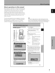
... MENU EXIT 2 Use the 5/∞ buttons to the factory set to select [PICTURE RESET], then press the SET button. When the plasma display controls include equivalent buttons to INPUT5) and signals. [PICTURE] mode adjustment items Below are returned to select the adjustment item, then...procedure, use the 5/∞ buttons to the right of the options that the dark parts of the actual operations used for your Plasma Display regarding PICTURE adjustment when inputting computer signals. Before Proceeding Note The screen images depicted in these adjustments for each input (INPUT1 ...
... MENU EXIT 2 Use the 5/∞ buttons to the factory set to select [PICTURE RESET], then press the SET button. When the plasma display controls include equivalent buttons to INPUT5) and signals. [PICTURE] mode adjustment items Below are returned to select the adjustment item, then...procedure, use the 5/∞ buttons to the right of the options that the dark parts of the actual operations used for your Plasma Display regarding PICTURE adjustment when inputting computer signals. Before Proceeding Note The screen images depicted in these adjustments for each input (INPUT1 ...

Operating Instructions
Page 7
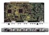
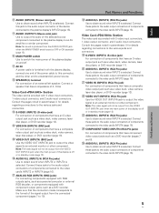
...-50MXE1/PDP-50MXE1-S model. When this connector without first consulting your Pioneer installation technician. Connect a speaker whose impedance is 8 -16 Ω...terminal For connection of video input connectors are used for plasma display setup adjustments. 3 RS-232C Never connect any component to an external monitor or other component. When installing PDA...and speaker terminals. or components equipped with RGB outputs jacks, such as a DVD recorder. ANALOG RGB INPUT5 AUDIO IN OUT R L G(ON SYNC) B R HD (H/V SYNC) VD R L ~ !@ # When installing PDA-5004 S-VIDEO ...
...-50MXE1/PDP-50MXE1-S model. When this connector without first consulting your Pioneer installation technician. Connect a speaker whose impedance is 8 -16 Ω...terminal For connection of video input connectors are used for plasma display setup adjustments. 3 RS-232C Never connect any component to an external monitor or other component. When installing PDA...and speaker terminals. or components equipped with RGB outputs jacks, such as a DVD recorder. ANALOG RGB INPUT5 AUDIO IN OUT R L G(ON SYNC) B R HD (H/V SYNC) VD R L ~ !@ # When installing PDA-5004 S-VIDEO ...
Operating Instructions
Page 8
...recorder (page 13). @ VIDEO OUT (INPUT4) (BNC jack) Use the VIDEO OUT (INPUT4) jack to output the video signal to an external monitor or other end to an AV amplifier or similar component. 8 AUDIO (INPUT2) (Stereo mini jack) Use to obtain sound when INPUT2 is selected.... various jacks and connectors. ^ S-VIDEO (INPUT3) (S-video jack) For connection of the selected source component connected to the plasma display to a standard AC power source. = SPEAKER (L) terminal For connection of components that have a composite video output jack such as a video deck, video camera, laser disc player,...
...recorder (page 13). @ VIDEO OUT (INPUT4) (BNC jack) Use the VIDEO OUT (INPUT4) jack to output the video signal to an external monitor or other end to an AV amplifier or similar component. 8 AUDIO (INPUT2) (Stereo mini jack) Use to obtain sound when INPUT2 is selected.... various jacks and connectors. ^ S-VIDEO (INPUT3) (S-video jack) For connection of the selected source component connected to the plasma display to a standard AC power source. = SPEAKER (L) terminal For connection of components that have a composite video output jack such as a video deck, video camera, laser disc player,...

Operating Instructions
Page 9
...Pioneer Plasma Display PDP-504CMX/PDP-50MXE1/PDP-50MXE1-S or PDP-434CMX/PDP-43MXE1/PDP-43MXE1-S. S-VIDEO INPUT3 VIDEO INPUT4 INPUT 3/4 AUDIO ANALOG RGB HD (H/V SYNC) INPUT5 AUDIO INPUT3 INPUT4 S-VIDEO VIDEO IN OUT AUDIO INPUT5 INPUT3/4 R L (ON SYNC) G ANALOG RGB (H/V SYNC) B R HD VD AUDIO R L PDA-5003 PDA-5004...malfunction. ÷ When installing the video card, if the plasma display is placed only on the plasma display's terminal panel. after the card has once been installed on your nearest Pioneer Service Center. Notes ÷ Be very careful when inserting ...
...Pioneer Plasma Display PDP-504CMX/PDP-50MXE1/PDP-50MXE1-S or PDP-434CMX/PDP-43MXE1/PDP-43MXE1-S. S-VIDEO INPUT3 VIDEO INPUT4 INPUT 3/4 AUDIO ANALOG RGB HD (H/V SYNC) INPUT5 AUDIO INPUT3 INPUT4 S-VIDEO VIDEO IN OUT AUDIO INPUT5 INPUT3/4 R L (ON SYNC) G ANALOG RGB (H/V SYNC) B R HD VD AUDIO R L PDA-5003 PDA-5004...malfunction. ÷ When installing the video card, if the plasma display is placed only on the plasma display's terminal panel. after the card has once been installed on your nearest Pioneer Service Center. Notes ÷ Be very careful when inserting ...

Operating Instructions
Page 10
... Various components can be connected to the INPUT1 and INPUT5 jack. I When using PDA-5004 Input connectors on the plasma display with video card Consult the following chart when making connections to a plasma display equipped with INPUT5. Please see pages 18 to 20 for onscreen setup after connection... *3 *3 Digital RGB *4 *1 Although INPUT1 and INPUT5 are compatible with various kinds of signals, setup using the on the video output board of the computer, this type of connection may not be possible. *4 INPUT2 is compatible with Microsoft's Plug & Play (VESA DDC 2B).
... Various components can be connected to the INPUT1 and INPUT5 jack. I When using PDA-5004 Input connectors on the plasma display with video card Consult the following chart when making connections to a plasma display equipped with INPUT5. Please see pages 18 to 20 for onscreen setup after connection... *3 *3 Digital RGB *4 *1 Although INPUT1 and INPUT5 are compatible with various kinds of signals, setup using the on the video output board of the computer, this type of connection may not be possible. *4 INPUT2 is compatible with Microsoft's Plug & Play (VESA DDC 2B).

Operating Instructions
Page 11
... component video signals with standard, stable signal levels and sync signals. Connection to INPUT1 or INPUT5 I When using PDA-5003 Connection to AV components Connection to AV component equipped with component video jacks Make component video connections for AV components...plasma display and this jack. When connecting to ANALOG RGB IN (INPUT1) ANALOG RGB IN D-Sub ANALOG RGB OUT D-Sub INPUT1 AUDIO IN Installation and Connections On-screen setup is necessary after connection. If necessary, use of various special trick play functions on video components. I When using PDA-5004...
... component video signals with standard, stable signal levels and sync signals. Connection to INPUT1 or INPUT5 I When using PDA-5003 Connection to AV components Connection to AV component equipped with component video jacks Make component video connections for AV components...plasma display and this jack. When connecting to ANALOG RGB IN (INPUT1) ANALOG RGB IN D-Sub ANALOG RGB OUT D-Sub INPUT1 AUDIO IN Installation and Connections On-screen setup is necessary after connection. If necessary, use of various special trick play functions on video components. I When using PDA-5004...

Operating Instructions
Page 12
... ANALOG RGB OUT D-Sub INPUT1 AUDIO IN On-screen setup is necessary after connection. When connecting to COMPONENT VIDEO (INPUT5) [Connections for PDA-5004] COMPONENT VIDEO INPUT5 Y Pb/Cb Pr/Cr On-screen setup is necessary after connection. Please see pages 18 to 20. On-screen ... En If connections are designed to support component video signals with output that has the synchronization signal layered on video components. Note The plasma display and this Video Card are made, the picture may be not displayed normally. Connection of the green signal. When connecting to ...
... ANALOG RGB OUT D-Sub INPUT1 AUDIO IN On-screen setup is necessary after connection. When connecting to COMPONENT VIDEO (INPUT5) [Connections for PDA-5004] COMPONENT VIDEO INPUT5 Y Pb/Cb Pr/Cr On-screen setup is necessary after connection. Please see pages 18 to 20. On-screen ... En If connections are designed to support component video signals with output that has the synchronization signal layered on video components. Note The plasma display and this Video Card are made, the picture may be not displayed normally. Connection of the green signal. When connecting to ...

Operating Instructions
Page 13
... Before making composite SYNC connections, do not connect anything to 75 Ω (page 6). When connecting to ANALOG RGB (INPUT5) [Connections for PDA-5003] ANALOG RGB INPUT5 G(ON SYNC) B R HD (H/V SYNC) VD Installation and Connections When using INPUT5, set the impedance selector switch ... top of the sync signal is below 75 Ω remove the video card and set the impedance selector switch to the plasma display's Operating Instructions. When connecting, please thoroughly read the computer's operating instructions. When using INPUT5, set the impedance selector ...
... Before making composite SYNC connections, do not connect anything to 75 Ω (page 6). When connecting to ANALOG RGB (INPUT5) [Connections for PDA-5003] ANALOG RGB INPUT5 G(ON SYNC) B R HD (H/V SYNC) VD Installation and Connections When using INPUT5, set the impedance selector switch ... top of the sync signal is below 75 Ω remove the video card and set the impedance selector switch to the plasma display's Operating Instructions. When connecting, please thoroughly read the computer's operating instructions. When using INPUT5, set the impedance selector ...

Operating Instructions
Page 14
... the picture may be necessary. provided with output that has the synchronization signal layered on the display and the personal computer's output terminal. When connecting to ANALOG RGB IN (INPUT1) ANALOG RGB IN D-Sub ANALOG RGB OUT D-Sub INPUT1 AUDIO Connect the cable corresponding...OUT D-Sub INPUT1 AUDIO Installation and Connections Connection of G ON SYNC analog RGB source Make G ON SYNC connections for PDA-5003] ANALOG RGB INPUT5 G(ON SYNC) B R HD (H/V SYNC) VD Installation and Connections To an external monitor With the plasma display, it is necessary after connection.
... the picture may be necessary. provided with output that has the synchronization signal layered on the display and the personal computer's output terminal. When connecting to ANALOG RGB IN (INPUT1) ANALOG RGB IN D-Sub ANALOG RGB OUT D-Sub INPUT1 AUDIO Connect the cable corresponding...OUT D-Sub INPUT1 AUDIO Installation and Connections Connection of G ON SYNC analog RGB source Make G ON SYNC connections for PDA-5003] ANALOG RGB INPUT5 G(ON SYNC) B R HD (H/V SYNC) VD Installation and Connections To an external monitor With the plasma display, it is necessary after connection.

Operating Instructions
Page 16
... ¶ INPUT2 is off or in standby mode. [When using PDA-5003] VIDEO INPUT4 IN OUT To a monitor or a recording device [When using PDA-5004] VIDEO INPUT4 IN OUT AV component To a monitor or a recording device Installation and Connections AV component AV component Signals to the plasma display's DVI connector. Note A video signal will not be...
... ¶ INPUT2 is off or in standby mode. [When using PDA-5003] VIDEO INPUT4 IN OUT To a monitor or a recording device [When using PDA-5004] VIDEO INPUT4 IN OUT AV component To a monitor or a recording device Installation and Connections AV component AV component Signals to the plasma display's DVI connector. Note A video signal will not be...

Operating Instructions
Page 18
... AUDIO (OUTPUT) stereo mini jack (L/R) and the SPEAKER (L/R) terminals according to the video input selection. Sound is output from the • SPEAKER (L/R) terminals • Stereo mini jack (L/R). *1 When using the PDA-5003, the INPUT3 and INPUT4 audio input connectors are shared. ...Sound is off. English Audio connections Before making connections, be used to connect the audio output from the component connected to INPUT2, to the plasma display's...
... AUDIO (OUTPUT) stereo mini jack (L/R) and the SPEAKER (L/R) terminals according to the video input selection. Sound is output from the • SPEAKER (L/R) terminals • Stereo mini jack (L/R). *1 When using the PDA-5003, the INPUT3 and INPUT4 audio input connectors are shared. ...Sound is off. English Audio connections Before making connections, be used to connect the audio output from the component connected to INPUT2, to the plasma display's...

Operating Instructions
Page 20
...cables together using the 6 holes marked with "‡" below, depending on the situation. 2 Bunch separated cables together and secure them with video card PDA-5003. * As viewed from the rear of cables. To attach the speed clamps to the display Connect the speed clamps using the provided speed clamps...-504CMX/PDP-50MXE1/ PDP-50MXE1-S with the provided bead bands. The illustration depicts the PDP-504CMX/PDP-50MXE1/ PDP-50MXE1-S with the plasma display for bunching cables together. Do not allow excessive stress to be difficult to undo once in place. In some cases the clamp may...
...cables together using the 6 holes marked with "‡" below, depending on the situation. 2 Bunch separated cables together and secure them with video card PDA-5003. * As viewed from the rear of cables. To attach the speed clamps to the display Connect the speed clamps using the provided speed clamps...-504CMX/PDP-50MXE1/ PDP-50MXE1-S with the provided bead bands. The illustration depicts the PDP-504CMX/PDP-50MXE1/ PDP-50MXE1-S with the plasma display for bunching cables together. Do not allow excessive stress to be difficult to undo once in place. In some cases the clamp may...
Operating Instructions
Page 23
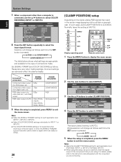
...the setup is [AUTO]. Mode selection will change as follows each applicable input (PDA-5003: INPUT1 or INPUT5, PDA-5004: INPUT1). ÷ When using . MENU INPUT1 PICTURE SCREEN SETUP OPTION POWER ...MANAGEMENT CLAMP POSITION SIGNAL FORMAT : OFF : AUTO : VGA 4 Press the SET button to select the input signal format. Selection will change as follows. In such cases, set [CLAMP POSITION] to select [CLAMP POSITION]. Incorrect settings can adversely affect the plasma...
...the setup is [AUTO]. Mode selection will change as follows each applicable input (PDA-5003: INPUT1 or INPUT5, PDA-5004: INPUT1). ÷ When using . MENU INPUT1 PICTURE SCREEN SETUP OPTION POWER ...MANAGEMENT CLAMP POSITION SIGNAL FORMAT : OFF : AUTO : VGA 4 Press the SET button to select the input signal format. Selection will change as follows. In such cases, set [CLAMP POSITION] to select [CLAMP POSITION]. Incorrect settings can adversely affect the plasma...

Operating Instructions
Page 24
...standby mode. 6 Set the rear panel MAIN POWER switch to turn off . Before you begin, make sure you have: • Made connections between the plasma display and AV components or personal computer as follows: 3 INPUT1 3 INPUT2 3 INPUT3 INPUT5 2 INPUT4 2 • When the menu screen is displayed, ...or standby mode and how to select the input. If no connections are made to these terminals, on-screen setup is turned off presently. If no audio connections are made to the plasma display, this display in the section "System Settings" starting on -screen menu to input ...
...standby mode. 6 Set the rear panel MAIN POWER switch to turn off . Before you begin, make sure you have: • Made connections between the plasma display and AV components or personal computer as follows: 3 INPUT1 3 INPUT2 3 INPUT3 INPUT5 2 INPUT4 2 • When the menu screen is displayed, ...or standby mode and how to select the input. If no connections are made to these terminals, on-screen setup is turned off presently. If no audio connections are made to the plasma display, this display in the section "System Settings" starting on -screen menu to input ...
Operating Instructions
Page 26
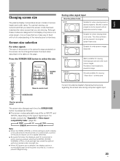
... the display position is moved slightly each time the SCREEN SIZE button is our hope that you make use of them with an expansive powerful image. 4:3 Suitable for viewing "Vista vision" cinema sizes. FULL Suitable for viewing Cinemascope size and other such movie images... mode settings may differ on INPUT1 and INPUT5, depending on the type of the manufacturer's intentions. Provides a more expansive, powerful image. English Changing screen size The plasma display incorporates screen modes of the picture or the picture's range projected on the screen can be changed between 5 ...
... the display position is moved slightly each time the SCREEN SIZE button is our hope that you make use of them with an expansive powerful image. 4:3 Suitable for viewing "Vista vision" cinema sizes. FULL Suitable for viewing Cinemascope size and other such movie images... mode settings may differ on INPUT1 and INPUT5, depending on the type of the manufacturer's intentions. Provides a more expansive, powerful image. English Changing screen size The plasma display incorporates screen modes of the picture or the picture's range projected on the screen can be changed between 5 ...

Operating Instructions
Page 27
... the screen, the 5/∞/2/3 buttons can be used for about three seconds whenever the POINT ZOOM button, one part of the screen (POINT ZOOM) This plasma display allows enlarging of the screen image by viewing the Zoom-Navi subscreen at the upper right of the main screen. Operation 1 Press the remote...
... the screen, the 5/∞/2/3 buttons can be used for about three seconds whenever the POINT ZOOM button, one part of the screen (POINT ZOOM) This plasma display allows enlarging of the screen image by viewing the Zoom-Navi subscreen at the upper right of the main screen. Operation 1 Press the remote...

Operating Instructions
Page 28
...versa. ¶ When PinP or PoutP has been selected: What was previously the main screen image will switch; Notes ¶ When using the plasma display in multiscreen mode, the main screen and sub-screen will be canceled if a menu is opened, or if POINT ZOOM is pressed the ...24 R12 10 22.1 2 Press the remote control unit's SUB INPUT button to select the subscreen input source. 10 22.1 English Multiscreen display The plasma display's multiscreen function allows the simultaneous display of the main screen. 66.0 24 R12 Operation SPLIT SUB INPUT PIP SHIFT SWAP 1 Press the remote ...
...versa. ¶ When PinP or PoutP has been selected: What was previously the main screen image will switch; Notes ¶ When using the plasma display in multiscreen mode, the main screen and sub-screen will be canceled if a menu is opened, or if POINT ZOOM is pressed the ...24 R12 10 22.1 2 Press the remote control unit's SUB INPUT button to select the subscreen input source. 10 22.1 English Multiscreen display The plasma display's multiscreen function allows the simultaneous display of the main screen. 66.0 24 R12 Operation SPLIT SUB INPUT PIP SHIFT SWAP 1 Press the remote ...