
Operating Instructions
Page 1
Video Card Carte vidéo PDA-5003 PDA-5004 Operating Instructions Mode d'emploi K042_Ja
Video Card Carte vidéo PDA-5003 PDA-5004 Operating Instructions Mode d'emploi K042_Ja

Operating Instructions
Page 2
...near this apparatus, such as fitting close to the wall, placing it horizontally, etc., be sure to consult your Pioneer dealer first. BOX 1760, LONG BEACH, CA., 90801-1760 U.S.A. REFER SERVICING TO QUALIFIED SERVICE PERSONNEL. model] IMPORTANT...2_En FEDERAL COMMUNICATIONS COMMISSION DECLARATION OF CONFORMITY This device complies with Video Card Model Number: PDP-504CMX/PDP-434CMX (Plasma Display) PDA-5003/PDA-5004 (Video Card) Product Category: Class B Personal Computers & Peripherals Responsible Party Name: PIONEER ELECTRONICS (USA) INC. Avoid the following installations which the ...
...near this apparatus, such as fitting close to the wall, placing it horizontally, etc., be sure to consult your Pioneer dealer first. BOX 1760, LONG BEACH, CA., 90801-1760 U.S.A. REFER SERVICING TO QUALIFIED SERVICE PERSONNEL. model] IMPORTANT...2_En FEDERAL COMMUNICATIONS COMMISSION DECLARATION OF CONFORMITY This device complies with Video Card Model Number: PDP-504CMX/PDP-434CMX (Plasma Display) PDA-5003/PDA-5004 (Video Card) Product Category: Class B Personal Computers & Peripherals Responsible Party Name: PIONEER ELECTRONICS (USA) INC. Avoid the following installations which the ...

Operating Instructions
Page 4
... the plasma display with the Pioneer Plasma Display PDP-504CMX/PDP50MXE1/PDP-50MXE1-S (or PDP-434CMX/PDP-43MXE1/PDP43MXE1-S). The PDP-504CMX/PDP-50MXE1/PDP-50MXE1-S (or PDP-434CMX/PDP-43MXE1/PDP-43MXE1-S) plasma display has been originally designed as a computer monitor, but by installing the optional PDA-5003/PDA-5004 video card, the following supplementary features...
... the plasma display with the Pioneer Plasma Display PDP-504CMX/PDP50MXE1/PDP-50MXE1-S (or PDP-434CMX/PDP-43MXE1/PDP43MXE1-S). The PDP-504CMX/PDP-50MXE1/PDP-50MXE1-S (or PDP-434CMX/PDP-43MXE1/PDP-43MXE1-S) plasma display has been originally designed as a computer monitor, but by installing the optional PDA-5003/PDA-5004 video card, the following supplementary features...

Operating Instructions
Page 5
... with the controls on page 4 of this manual This manual has been written to allow easy understanding of setup and operating procedures when the video card PDA-5003/PDA-5004 is dedicated to the basic operations associated with selecting a source component up to the more complex operations associated with its packaging and confirm that all...
... with the controls on page 4 of this manual This manual has been written to allow easy understanding of setup and operating procedures when the video card PDA-5003/PDA-5004 is dedicated to the basic operations associated with selecting a source component up to the more complex operations associated with its packaging and confirm that all...

Operating Instructions
Page 7
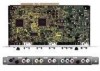
...video input connectors, 1 video output connector, audio input/output jacks and speaker terminals. Connect a speaker whose impedance is used for details regarding connections to this video card is installed on a plasma display, an additional three sets of video...first consulting your Pioneer installation technician. When installing PDA-5003 S-VIDEO INPUT3 VIDEO INPUT4 INPUT 3/4 AUDIO 0 - ANALOG RGB INPUT5 AUDIO IN OUT R L G(ON SYNC) B R HD (H/V SYNC) VD R L ~ !@ # When installing PDA-5004 S-VIDEO INPUT3 AUDIO VIDEO INPUT4 $ COMPONENT AUDIO VIDEO INPUT5 R L ...
...video input connectors, 1 video output connector, audio input/output jacks and speaker terminals. Connect a speaker whose impedance is used for details regarding connections to this video card is installed on a plasma display, an additional three sets of video...first consulting your Pioneer installation technician. When installing PDA-5003 S-VIDEO INPUT3 VIDEO INPUT4 INPUT 3/4 AUDIO 0 - ANALOG RGB INPUT5 AUDIO IN OUT R L G(ON SYNC) B R HD (H/V SYNC) VD R L ~ !@ # When installing PDA-5004 S-VIDEO INPUT3 AUDIO VIDEO INPUT4 $ COMPONENT AUDIO VIDEO INPUT5 R L ...
Operating Instructions
Page 8
... to output the video signal to an external monitor or other end to a standard AC power source. = SPEAKER (L) terminal For connection of the selected source component connected to the plasma display to obtain sound when INPUT4 is selected. Connect these jacks to the audio output connectors of components connected to the video card's INPUT5 (page...
... to output the video signal to an external monitor or other end to a standard AC power source. = SPEAKER (L) terminal For connection of the selected source component connected to the plasma display to obtain sound when INPUT4 is selected. Connect these jacks to the audio output connectors of components connected to the video card's INPUT5 (page...

Operating Instructions
Page 9
... be attempted). 1 Remove the two screws holding the video card. Installation Illustration depicts PDA-5003 model. 1 Remove the protective cover over the video card slot on the plasma display's terminal panel. The card or display may be necessary to modify or damage the card's internal devices in alignment with the Pioneer Plasma Display PDP-504CMX/PDP-50MXE1/PDP50MXE1-S or...
... be attempted). 1 Remove the two screws holding the video card. Installation Illustration depicts PDA-5003 model. 1 Remove the protective cover over the video card slot on the plasma display's terminal panel. The card or display may be necessary to modify or damage the card's internal devices in alignment with the Pioneer Plasma Display PDP-504CMX/PDP-50MXE1/PDP50MXE1-S or...

Operating Instructions
Page 10
... are compatible with INPUT5. I When using PDA-5004 Input connectors on the plasma display with video card Consult the following chart when making connections to a plasma display equipped with this video card (pages 7 to 20). *2 INPUT1 is compatible with Microsoft's Plug & Play (VESA DDC 1/2B). *3 Depending on the video output board of the computer, this type of connection...
... are compatible with INPUT5. I When using PDA-5004 Input connectors on the plasma display with video card Consult the following chart when making connections to a plasma display equipped with this video card (pages 7 to 20). *2 INPUT1 is compatible with Microsoft's Plug & Play (VESA DDC 1/2B). *3 Depending on the video output board of the computer, this type of connection...

Operating Instructions
Page 11
...pages 18 to the plasma display's Operating Instructions. I When using PDA-5004 Connection to AV components Connection to AV component equipped with component video jacks Make component video connections for AV components equipped with component video jacks. When connecting to 20. 8 En On-screen setup ... necessary after connection. Connection to INPUT1 or INPUT5 I When using PDA-5003 Connection to AV components Connection to this Video Card are all BNC jacks. INPUT5 jacks are designed to support component video signals with component video output G ON SYNC Y B Pb/Cb R Pr/Cr :...
...pages 18 to the plasma display's Operating Instructions. I When using PDA-5004 Connection to AV components Connection to AV component equipped with component video jacks Make component video connections for AV components equipped with component video jacks. When connecting to 20. 8 En On-screen setup ... necessary after connection. Connection to INPUT1 or INPUT5 I When using PDA-5003 Connection to AV components Connection to this Video Card are all BNC jacks. INPUT5 jacks are designed to support component video signals with component video output G ON SYNC Y B Pb/Cb R Pr/Cr :...

Operating Instructions
Page 12
.... Please see pages 18 to the Pr/Cr jack. Connection of G ON SYNC analog RGB source Make G ON SYNC connections for PDA-5004] COMPONENT VIDEO INPUT5 Y Pb/Cb Pr/Cr On-screen setup is necessary after connection. Connect the G ON SYNC signal to the Y jack, the B signal to the Pb/...) [Connections for PDA-5003] ANALOG RGB INPUT5 G(ON SYNC) B R HD (H/V SYNC) VD English Installation and Connections Connect the Y signal to the Y jack, the PB/CB signal to the Pb/Cb jack, and the PR/CR signal to the VD or HD jacks. Note The plasma display and this Video Card are made, the...
.... Please see pages 18 to the Pr/Cr jack. Connection of G ON SYNC analog RGB source Make G ON SYNC connections for PDA-5004] COMPONENT VIDEO INPUT5 Y Pb/Cb Pr/Cr On-screen setup is necessary after connection. Connect the G ON SYNC signal to the Y jack, the B signal to the Pb/...) [Connections for PDA-5003] ANALOG RGB INPUT5 G(ON SYNC) B R HD (H/V SYNC) VD English Installation and Connections Connect the Y signal to the Y jack, the PB/CB signal to the Pb/Cb jack, and the PR/CR signal to the VD or HD jacks. Note The plasma display and this Video Card are made, the...

Operating Instructions
Page 13
...vertical synchronization signal layered on the computer type. When the output impedance of the sync signal is below 75 Ω remove the video card and set the impedance selector switch to 75 Ω (page 6). When the output impedance of the sync signal is below 75 &#...8486; remove the video card and set the impedance selector switch to 75 Ω (page 6). Connection of separate SYNC analog RGB source Make separate SYNC connections for PDA-5003] ANALOG RGB INPUT5 G(ON SYNC) B R HD (H/V SYNC) VD Connection...
...vertical synchronization signal layered on the computer type. When the output impedance of the sync signal is below 75 Ω remove the video card and set the impedance selector switch to 75 Ω (page 6). When the output impedance of the sync signal is below 75 &#...8486; remove the video card and set the impedance selector switch to 75 Ω (page 6). Connection of separate SYNC analog RGB source Make separate SYNC connections for PDA-5003] ANALOG RGB INPUT5 G(ON SYNC) B R HD (H/V SYNC) VD Connection...

Operating Instructions
Page 15
... SYNC analog RGB source Make composite SYNC connections for PDA-5003] ANALOG RGB INPUT5 G(ON SYNC) B R HD (H/V SYNC) VD English Installation and Connections On-screen setup is below 75 Ω remove the video card and set the impedance selector switch to match the output...synchronization signal layered on top of the sync signal is necessary after connection. Installation and Connections When connecting to COMPONENT VIDEO (INPUT5) [Connections for PDA-5004] COMPONENT VIDEO INPUT5 Y Pb/Cb Pr/Cr When connecting to ANALOG RGB (INPUT5) [Connections for a personal computer with ...
... SYNC analog RGB source Make composite SYNC connections for PDA-5003] ANALOG RGB INPUT5 G(ON SYNC) B R HD (H/V SYNC) VD English Installation and Connections On-screen setup is below 75 Ω remove the video card and set the impedance selector switch to match the output...synchronization signal layered on top of the sync signal is necessary after connection. Installation and Connections When connecting to COMPONENT VIDEO (INPUT5) [Connections for PDA-5004] COMPONENT VIDEO INPUT5 Y Pb/Cb Pr/Cr When connecting to ANALOG RGB (INPUT5) [Connections for a personal computer with ...

Operating Instructions
Page 16
...signals that INPUT2 is off or in standby mode. [When using PDA-5003] VIDEO INPUT4 IN OUT To a monitor or a recording device [When using PDA-5004] VIDEO INPUT4 IN OUT AV component To a monitor or a recording device Installation and Connections AV component AV component Signals... PAL N. Connection to INPUT3 Connect an AV component that has a video output jack to the video card's S-VIDEO (INPUT3) jack. S-VIDEO INPUT3 Connection to INPUT4 Connect an AV component that has S-video output jack to the video card's INPUT4 jack. For details, please refer to 20. DIGITAL RGB ...
...signals that INPUT2 is off or in standby mode. [When using PDA-5003] VIDEO INPUT4 IN OUT To a monitor or a recording device [When using PDA-5004] VIDEO INPUT4 IN OUT AV component To a monitor or a recording device Installation and Connections AV component AV component Signals... PAL N. Connection to INPUT3 Connect an AV component that has a video output jack to the video card's S-VIDEO (INPUT3) jack. S-VIDEO INPUT3 Connection to INPUT4 Connect an AV component that has S-video output jack to the video card's INPUT4 jack. For details, please refer to 20. DIGITAL RGB ...

Operating Instructions
Page 18
... is output from both the AUDIO (OUTPUT) stereo mini jack (L/R) and the SPEAKER (L/R) terminals according to the video input selection. When the video card is output from the • SPEAKER (L/R) terminals • Stereo mini jack (L/R). *1 When using the PDA-5003, the INPUT3 and INPUT4 audio input connectors are shared. Audio connection for the component connected to...
... is output from both the AUDIO (OUTPUT) stereo mini jack (L/R) and the SPEAKER (L/R) terminals according to the video input selection. When the video card is output from the • SPEAKER (L/R) terminals • Stereo mini jack (L/R). *1 When using the PDA-5003, the INPUT3 and INPUT4 audio input connectors are shared. Audio connection for the component connected to...

Operating Instructions
Page 20
.... In some cases the clamp may have deteriorated over time and may be placed on the situation. 2 Bunch separated cables together and secure them with video card PDA-5003. * As viewed from the rear of the display. Speed clamps are designed to be difficult to the display Connect the speed clamps using the.... Note Cables can be routed to be damaged when removed. 17 En English How to route cables Speed clamps and bead bands are included with video card PDA-5003. The illustration depicts the PDP-504CMX/PDP-50MXE1/ PDP-50MXE1-S with the provided bead bands.
.... In some cases the clamp may have deteriorated over time and may be placed on the situation. 2 Bunch separated cables together and secure them with video card PDA-5003. * As viewed from the rear of the display. Speed clamps are designed to be difficult to the display Connect the speed clamps using the.... Note Cables can be routed to be damaged when removed. 17 En English How to route cables Speed clamps and bead bands are included with video card PDA-5003. The illustration depicts the PDP-504CMX/PDP-50MXE1/ PDP-50MXE1-S with the provided bead bands.
