

User Manual
Page 1
... en japonais. Si vous vivez au Canada ou aux États-Unis, reportezvous aux instructions en français ou en anglais. Plasma Display Écran à plasma PDP-507CMX PDP-607CMX Operating Instructions Mode d'emploi Contents related to system specifications, power requirements, accessories, and other information differ with respect to the instructions written...
... en japonais. Si vous vivez au Canada ou aux États-Unis, reportezvous aux instructions en français ou en anglais. Plasma Display Écran à plasma PDP-507CMX PDP-607CMX Operating Instructions Mode d'emploi Contents related to system specifications, power requirements, accessories, and other information differ with respect to the instructions written...
User Manual
Page 3
.... Note for Dealers: After installation, be sure to deliver this PIONEER product. Notes on Installation Work: This product is installed by mistake in installation or mounting, misuse, modification or a natural disaster. Always have an installation specialist or your Plasma Display, please read the "Safety Precautions" and these "Operating Instructions" carefully so you...
.... Note for Dealers: After installation, be sure to deliver this PIONEER product. Notes on Installation Work: This product is installed by mistake in installation or mounting, misuse, modification or a natural disaster. Always have an installation specialist or your Plasma Display, please read the "Safety Precautions" and these "Operating Instructions" carefully so you...

User Manual
Page 6
... Support Division P.O. For warranty information please see the Limited Warranty sheet included with Video Card Model Number: PDP-507CMX/PDP-607CMX (Plasma Display) PDA-5003/PDA-5004 (Video Card) Product Category: Class B Personal Computers & Peripherals Responsible Party Name: PIONEER ELECTRONICS SERVICE, INC. Phone Number: 800-421-1625 For Business Customer URL: http://www.pioneerelectronics.com...
... Support Division P.O. For warranty information please see the Limited Warranty sheet included with Video Card Model Number: PDP-507CMX/PDP-607CMX (Plasma Display) PDA-5003/PDA-5004 (Video Card) Product Category: Class B Personal Computers & Peripherals Responsible Party Name: PIONEER ELECTRONICS SERVICE, INC. Phone Number: 800-421-1625 For Business Customer URL: http://www.pioneerelectronics.com...
User Manual
Page 7
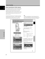
...3 How to use this manual 3 Checking supplied accessories 5 Part Names and Functions 6 Main unit 6 Remote control unit 7 Connection panel (PDP-507CMX 9 Connection panel (PDP-607CMX 10 Installation and Connections 11 Installation of the unit 11 Connection to a personal computer 13 Audio connections 14 Power cord connection 15 How... current status 20 Changing screen size 21 Enlarging one part of the screen (POINT ZOOM 22 Multiscreen display 23 Automatic power-off (POWER MANAGEMENT 24 PICTURE/SCREEN Adjustment 25 PICTURE adjustment 25 Adjusting screen POSITION, CLOCK, and PHASE
...3 How to use this manual 3 Checking supplied accessories 5 Part Names and Functions 6 Main unit 6 Remote control unit 7 Connection panel (PDP-507CMX 9 Connection panel (PDP-607CMX 10 Installation and Connections 11 Installation of the unit 11 Connection to a personal computer 13 Audio connections 14 Power cord connection 15 How... current status 20 Changing screen size 21 Enlarging one part of the screen (POINT ZOOM 22 Multiscreen display 23 Automatic power-off (POWER MANAGEMENT 24 PICTURE/SCREEN Adjustment 25 PICTURE adjustment 25 Adjusting screen POSITION, CLOCK, and PHASE

User Manual
Page 8
...screen size appearance will differ depending on input signal. ¶ Free Installation Configuration - PDP-507CMX: While producing a large 50" screen image, the display is provided with features giving it high dependability in commercial applications, including the ability to... suppress peak luminance in operating environment. Such features provide safety and highendurance under conditions of commercial use. ¶ Improved usability User convenience has been improved by Pioneer...
...screen size appearance will differ depending on input signal. ¶ Free Installation Configuration - PDP-507CMX: While producing a large 50" screen image, the display is provided with features giving it high dependability in commercial applications, including the ability to... suppress peak luminance in operating environment. Such features provide safety and highendurance under conditions of commercial use. ¶ Improved usability User convenience has been improved by Pioneer...

User Manual
Page 9
... have been received (page 5), it has been confirmed that would seem most logical for correct operation of the Plasma Display with adjusting the Plasma Display picture to match the requirements of specific components and personal preferences. The section "System Settings" starting on page 17 ...look over the section "Part Names and Functions" starting on the connections made, this section may or may not be necessary. Menu display examples MENU PICTURE SCREEN CONTRAST BRIGHTNESS H.ENHANCE V. Before Proceeding 3 En English Before Proceeding How to use this manual This manual is ...
... have been received (page 5), it has been confirmed that would seem most logical for correct operation of the Plasma Display with adjusting the Plasma Display picture to match the requirements of specific components and personal preferences. The section "System Settings" starting on page 17 ...look over the section "Part Names and Functions" starting on the connections made, this section may or may not be necessary. Menu display examples MENU PICTURE SCREEN CONTRAST BRIGHTNESS H.ENHANCE V. Before Proceeding 3 En English Before Proceeding How to use this manual This manual is ...
User Manual
Page 10
... include equivalent buttons to those buttons found on the remote control unit, the commands can be performed on the main Plasma Display itself. The following illustrations are provided to allow you to the operating controls found on the remote control unit, with the exception of the actual .... some difference will refer to confirm whether the operation is described in these Operating Instructions should be seen in practice, depending on the screen item displayed and its proper operating order.
... include equivalent buttons to those buttons found on the remote control unit, the commands can be performed on the main Plasma Display itself. The following illustrations are provided to allow you to the operating controls found on the remote control unit, with the exception of the actual .... some difference will refer to confirm whether the operation is described in these Operating Instructions should be seen in practice, depending on the screen item displayed and its proper operating order.

User Manual
Page 12
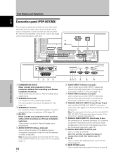
... 4 Handles Operation panel on the main unit 5 STANDBY/ON button ( ) Press to put the display in standby mode: The indicator lights red (page 19). VOL + 89 0 PDP-507CMX 1 STANDBY ON 23 PDP-607CMX 31 Main unit 1 Remote control sensor Point the remote control toward the remote sensor to [AUTO... SCREEN SIZE - Part Names and Functions 6 En English Part Names and Functions Main unit Main unit 4 (PDP-507CMX) 4 (PDP-607CMX) Operation panel on -screen menu (pages 17 to 36). 7 DISPLAY/SET button Use to confirm onscreen menu selections, and to change settings (pages 17 to 36). When flashing,...
... 4 Handles Operation panel on the main unit 5 STANDBY/ON button ( ) Press to put the display in standby mode: The indicator lights red (page 19). VOL + 89 0 PDP-507CMX 1 STANDBY ON 23 PDP-607CMX 31 Main unit 1 Remote control sensor Point the remote control toward the remote sensor to [AUTO... SCREEN SIZE - Part Names and Functions 6 En English Part Names and Functions Main unit Main unit 4 (PDP-507CMX) 4 (PDP-607CMX) Operation panel on -screen menu (pages 17 to 36). 7 DISPLAY/SET button Use to confirm onscreen menu selections, and to change settings (pages 17 to 36). When flashing,...

User Manual
Page 13
... this button to move the position of the screen (page 22). ! When this occurs, replace all batteries with multiscreen display, use this button to switch between main screen and subscreen (page 23). # PIP SHIFT button When using computer signal input, automatically sets the [POSITION], [CLOCK] ... (pages 17 to mute the volume (page 20). 9 ID NO. STANDBY/ON button ( ) Press to put the unit in operation or standby mode (page 19). = DISPLAY button Press to view the unit's current input and setup mode (page 20). ~ POINT ZOOM button Use to select and enlarge one part of subscreen...
... this button to move the position of the screen (page 22). ! When this occurs, replace all batteries with multiscreen display, use this button to switch between main screen and subscreen (page 23). # PIP SHIFT button When using computer signal input, automatically sets the [POSITION], [CLOCK] ... (pages 17 to mute the volume (page 20). 9 ID NO. STANDBY/ON button ( ) Press to put the unit in operation or standby mode (page 19). = DISPLAY button Press to view the unit's current input and setup mode (page 20). ~ POINT ZOOM button Use to select and enlarge one part of subscreen...

User Manual
Page 14
...may result, leading to 7 m from the unit and within a 30 angle on each side of infrared rays discharged from the Plasma Display, hampering reception of time, remove the batteries and store them separately. Should this occur, move the component to a position further away...control unit is operated by an infrared remote control unit near this unit's remote control unit may result, leading to the picture displayed. When disposing of used batteries, please comply with governmental regulations or environmental public institution's rules that component's reception of fire, personal...
...may result, leading to 7 m from the unit and within a 30 angle on each side of infrared rays discharged from the Plasma Display, hampering reception of time, remove the batteries and store them separately. Should this occur, move the component to a position further away...control unit is operated by an infrared remote control unit near this unit's remote control unit may result, leading to the picture displayed. When disposing of used batteries, please comply with governmental regulations or environmental public institution's rules that component's reception of fire, personal...

User Manual
Page 15
...to connect a computer. Audio input/ output and speaker output terminals are used for Plasma Display setup adjustments. 4 RS-232C Never connect any component to this connector without first consulting your Pioneer installation technician. These connectors are also provided. Connect the audio output jack of 6 &#...standby) (page 14). 6 AUDIO (INPUT1) (Stereo mini jack) Use to an external monitor or other component. English Connection panel (PDP-507CMX) The connection panel is selected. Note: No sound is produced from the ANALOG RGB OUT (INPUT1) terminal when the main power of...
...to connect a computer. Audio input/ output and speaker output terminals are used for Plasma Display setup adjustments. 4 RS-232C Never connect any component to this connector without first consulting your Pioneer installation technician. These connectors are also provided. Connect the audio output jack of 6 &#...standby) (page 14). 6 AUDIO (INPUT1) (Stereo mini jack) Use to an external monitor or other component. English Connection panel (PDP-507CMX) The connection panel is selected. Note: No sound is produced from the ANALOG RGB OUT (INPUT1) terminal when the main power of...
User Manual
Page 16
...INPUT1 is selected. Audio input/ output and speaker output terminals are used for Plasma Display setup adjustments. 2 SPEAKER (R) terminal For connection of components connected to INPUT1 to...0 6 AUDIO (INPUT1) (Stereo mini jack) Use to these connectors without first consulting your Pioneer installation technician. Note: No sound is produced from the AUDIO (OUTPUT) jack when the MAIN... audio of a personal computer (PC) or similar component. English Part Names and Functions Connection panel (PDP-607CMX) The connection panel is off . Make sure that has an impedance of 6 Ω ...
...INPUT1 is selected. Audio input/ output and speaker output terminals are used for Plasma Display setup adjustments. 2 SPEAKER (R) terminal For connection of components connected to INPUT1 to...0 6 AUDIO (INPUT1) (Stereo mini jack) Use to these connectors without first consulting your Pioneer installation technician. Note: No sound is produced from the AUDIO (OUTPUT) jack when the MAIN... audio of a personal computer (PC) or similar component. English Part Names and Functions Connection panel (PDP-607CMX) The connection panel is off . Make sure that has an impedance of 6 Ω ...
User Manual
Page 17
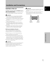
... shown. English Français Installation and Connections Installation of the unit Installation using the optional PIONEER stand or other mounting brackets ÷ Please be sure to move the Plasma Display by holding the rear handles in .) to fall or be damage. ÷ After installation,... the instructions provided or other applicable installation instructions. ÷ Two or more information. CAUTION ÷ Handles should always be done by Pioneer. Refer to the side view diagram in .) into the main unit from falling. CAUTION When this unit is installed on a flat,...
... shown. English Français Installation and Connections Installation of the unit Installation using the optional PIONEER stand or other mounting brackets ÷ Please be sure to move the Plasma Display by holding the rear handles in .) to fall or be damage. ÷ After installation,... the instructions provided or other applicable installation instructions. ÷ Two or more information. CAUTION ÷ Handles should always be done by Pioneer. Refer to the side view diagram in .) into the main unit from falling. CAUTION When this unit is installed on a flat,...

User Manual
Page 19
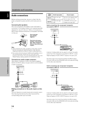
.... Connection to INPUT2 A computer equipped with the computer or sold separately may be connected to 43) for information regarding signals and display formats supported by tightening the terminal screws on the computer type. Following completing connections, on -screen setup is necessary. See Appendix... 2-2/2 (page 45) when making connections to INPUT1. ¶ See Appendix 1 (pages 42 to the Plasma Display's DVI connector. Following completing connections, on -screen setup is possible to output the video signal to 18 for the connection. ¶ This...
.... Connection to INPUT2 A computer equipped with the computer or sold separately may be connected to 43) for information regarding signals and display formats supported by tightening the terminal screws on the computer type. Following completing connections, on -screen setup is necessary. See Appendix... 2-2/2 (page 45) when making connections to INPUT1. ¶ See Appendix 1 (pages 42 to the Plasma Display's DVI connector. Following completing connections, on -screen setup is possible to output the video signal to 18 for the connection. ¶ This...
User Manual
Page 20
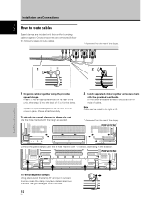
...cords to confirm that the audio component's power and the unit's main power is output from the component connected to INPUT2, to the Plasma Display's AUDIO (INPUT2) stereo mini jack (L/R). Insecure connections will produce excessive load on this unit. 12 mm Twist exposed wire strands together. ... (L/R) terminals according to the video input selection. Connecting the speakers This unit is output from the component connected to INPUT1, to the Plasma Display's AUDIO (INPUT1) stereo mini jack (L/R). Push tab to the open position, and insert the wire. Sound is off. This will result in...
...cords to confirm that the audio component's power and the unit's main power is output from the component connected to INPUT2, to the Plasma Display's AUDIO (INPUT2) stereo mini jack (L/R). Insecure connections will produce excessive load on this unit. 12 mm Twist exposed wire strands together. ... (L/R) terminals according to the video input selection. Connecting the speakers This unit is output from the component connected to INPUT1, to the Plasma Display's AUDIO (INPUT1) stereo mini jack (L/R). Push tab to the open position, and insert the wire. Sound is off. This will result in...

User Manual
Page 21
... V to the unit, first turn off the main unit's power switch, and then disconnect the power cord from its wall outlet. ÷ For the Plasma Display, use an outlet with a ground terminal. CAUTION ÷ Use only the power cord provided. ÷ The wall outlet used to provide electricity to this monitor...
... V to the unit, first turn off the main unit's power switch, and then disconnect the power cord from its wall outlet. ÷ For the Plasma Display, use an outlet with a ground terminal. CAUTION ÷ Use only the power cord provided. ÷ The wall outlet used to provide electricity to this monitor...
User Manual
Page 22
...Do not allow excessive stress to undo once in place. PDP-507CMX Connect the speed clamps using the provided speed clamps. Please attach carefully. To attach the speed clamps to the right or left. * As viewed from the rear of the display. 12 Installation and Connections 1 Organize cables together using the...into the back of 1 to fix the clamp. English Installation and Connections How to route cables. * As viewed from the rear of the display. PDP-607CMX To remove speed clamps Using pliers, twist the clamp 90° and pull it outward. Insert 1 into an appropriate hole on the situation....
...Do not allow excessive stress to undo once in place. PDP-507CMX Connect the speed clamps using the provided speed clamps. Please attach carefully. To attach the speed clamps to the right or left. * As viewed from the rear of the display. 12 Installation and Connections 1 Organize cables together using the...into the back of 1 to fix the clamp. English Installation and Connections How to route cables. * As viewed from the rear of the display. PDP-607CMX To remove speed clamps Using pliers, twist the clamp 90° and pull it outward. Insert 1 into an appropriate hole on the situation....
User Manual
Page 23
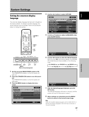
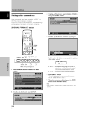
... the 2/3 buttons to select [OPTION]. STANDBY/ ON 4 Use the 2/3 buttons to select the desired language. System Settings MENU 2/3 SET 5/∞ Remote control unit STANDBY/ON DISPLAY MENU / SET INPUT SCREEN SIZE - The STANDBY/ON indicator on the front panel will light red. 2 Press the STANDBY/ON button to... display the menu screen. The STANDBY/ON indicator on the front panel will light green. 3 Press the MENU button to turn the power ON. Each time ...
... the 2/3 buttons to select [OPTION]. STANDBY/ ON 4 Use the 2/3 buttons to select the desired language. System Settings MENU 2/3 SET 5/∞ Remote control unit STANDBY/ON DISPLAY MENU / SET INPUT SCREEN SIZE - The STANDBY/ON indicator on the front panel will light red. 2 Press the STANDBY/ON button to... display the menu screen. The STANDBY/ON indicator on the front panel will light green. 3 Press the MENU button to turn the power ON. Each time ...
User Manual
Page 24
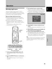
... time the 2/3 buttons are pressed, the selection alternates as they apply to the type of components connected. [SIGNAL FORMAT] setup 3 Use the 5/∞ buttons to display the menu screen. E N H A N C E SETUP : : : : INPUT1 OPTION 0 0 0 0 PICTURE RESET SET ENTER MENU EXIT 2 Use the 2/3 buttons to exit the menu screen. System Settings MENU 2/3 SET 5/∞...
... time the 2/3 buttons are pressed, the selection alternates as they apply to the type of components connected. [SIGNAL FORMAT] setup 3 Use the 5/∞ buttons to display the menu screen. E N H A N C E SETUP : : : : INPUT1 OPTION 0 0 0 0 PICTURE RESET SET ENTER MENU EXIT 2 Use the 2/3 buttons to exit the menu screen. System Settings MENU 2/3 SET 5/∞...
User Manual
Page 25
...INPUT SCREEN SIZE - The STANDBY/ON indicator may cause a phenomenon known as described in the section "System Settings" starting on the front panel will be displayed: INPUT1 CAUTION UNSUPPORTED SIGNAL FH: 86.7kHz FV: 88.5Hz - STANDBY/ON INPUT VOL +/- VOL + 3 Press the INPUT button to select the ...input. ÷ When the menu screen is displayed, changing the signal input will light red. 2 Press the STANDBY/ON button to turn off , put the unit in standby mode. 6 Set the rear...
...INPUT SCREEN SIZE - The STANDBY/ON indicator may cause a phenomenon known as described in the section "System Settings" starting on the front panel will be displayed: INPUT1 CAUTION UNSUPPORTED SIGNAL FH: 86.7kHz FV: 88.5Hz - STANDBY/ON INPUT VOL +/- VOL + 3 Press the INPUT button to select the ...input. ÷ When the menu screen is displayed, changing the signal input will light red. 2 Press the STANDBY/ON button to turn off , put the unit in standby mode. 6 Set the rear...


