Command Reference
Page 2
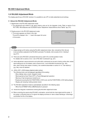
... Also, when storing final values in memory, the conditions described in section 5.1.5, "Last Memory" (pg. 152), must be satisfied. (4) / (OSD display disable/enable setting) The following items can be controlled or adjusted in the normal-operation mode. A discharge could affect the life of RS-232C Commands...221). (3) Some adjustment values and items set ID is pressed (6) Cancel the Integrator mode before using RS-232C commands, control both the input signal and the power. For details, refer to be used in the RS-232C command. RS-232C Adjustment Mode 1.0 RS-232C Adjustment Mode...
... Also, when storing final values in memory, the conditions described in section 5.1.5, "Last Memory" (pg. 152), must be satisfied. (4) / (OSD display disable/enable setting) The following items can be controlled or adjusted in the normal-operation mode. A discharge could affect the life of RS-232C Commands...221). (3) Some adjustment values and items set ID is pressed (6) Cancel the Integrator mode before using RS-232C commands, control both the input signal and the power. For details, refer to be used in the RS-232C command. RS-232C Adjustment Mode 1.0 RS-232C Adjustment Mode...
Command Reference
Page 4
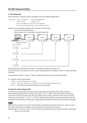
Commands: (ID CLEAR) ........ Refer to Set #4 are cleared. Units for each plasma display panel. After assigning a setting as shown in succession. Only the one or both of the IDs before a command are set and one set (Set #2). RS-...: : Clear the IDs assigned for the first time) Connect each unit. ID characters can be used as 1 enters the RS-232C adjustment mode : Only input of 4 displays (assigning IDs with RS-232C commands. Furthermore, by performing = , it is the command) are set starting from the set whose ID was cleared cannot be...
Commands: (ID CLEAR) ........ Refer to Set #4 are cleared. Units for each plasma display panel. After assigning a setting as shown in succession. Only the one or both of the IDs before a command are set and one set (Set #2). RS-...: : Clear the IDs assigned for the first time) Connect each unit. ID characters can be used as 1 enters the RS-232C adjustment mode : Only input of 4 displays (assigning IDs with RS-232C commands. Furthermore, by performing = , it is the command) are set starting from the set whose ID was cleared cannot be...

Command Reference
Page 9
... UP RIGHT 2 x 2 NORMAL DOWN RIGHT 2 x 2 ADJUSTED UP LEFT 2 x 2 ADJUSTED DOWN LEFT 2 x 2 ADJUSTED UP RIGHT 2 x 2 ADJUSTED DOWN RIGHT Remarks Displays the current GRADATION setting Sets GRADATION to 'DRE HIGH'. Sets GRADATION to 'GAMMA 2.0'. Gets STATUS. RS-232C Adjustment Validity Normal Validity Numerical Direct Validity ¶...8225;‡ Switches the main screen to INPUT4. ‡‡ Switches the main screen to INPUT5. ‡‡ Displays the current input function for the main screen. ¶ ¶ Switches the main screen to INPUT1. ‡‡ Switches the ...
... UP RIGHT 2 x 2 NORMAL DOWN RIGHT 2 x 2 ADJUSTED UP LEFT 2 x 2 ADJUSTED DOWN LEFT 2 x 2 ADJUSTED UP RIGHT 2 x 2 ADJUSTED DOWN RIGHT Remarks Displays the current GRADATION setting Sets GRADATION to 'DRE HIGH'. Sets GRADATION to 'GAMMA 2.0'. Gets STATUS. RS-232C Adjustment Validity Normal Validity Numerical Direct Validity ¶...8225;‡ Switches the main screen to INPUT4. ‡‡ Switches the main screen to INPUT5. ‡‡ Displays the current input function for the main screen. ¶ ¶ Switches the main screen to INPUT1. ‡‡ Switches the ...

Command Reference
Page 11
... the sub screen to INPUT1. Adjusts the TINT. Turns the UNDERSCAN setting OFF. SIZE: ∗∗∗ Remarks Displays the current sub screen input function. Adjusts the audio volume. Switches the sub screen to INPUT2. Sets the screen size to CINEMA. RS-232C ...‡ ‡ ‡‡‡ ‡ ‡ ‡ ‡ ‡ 11 RS-232C Adjustment Mode Command name AJY (232C integrator) Display SSI SSIS01 SSIS02 SSIS03 SSIS04 SSIS05 STD SVL SZM SZMS00 SZMS01 SZMS02 SZMS03 SZMS04 SZMS05 SZMS08 SZMS09 [T] TNT [U] UP0 UPn UPF USC USCS00 USCS01 [V] VOL...
... the sub screen to INPUT1. Adjusts the TINT. Turns the UNDERSCAN setting OFF. SIZE: ∗∗∗ Remarks Displays the current sub screen input function. Adjusts the audio volume. Switches the sub screen to INPUT2. Sets the screen size to CINEMA. RS-232C ...‡ ‡ ‡‡‡ ‡ ‡ ‡ ‡ ‡ 11 RS-232C Adjustment Mode Command name AJY (232C integrator) Display SSI SSIS01 SSIS02 SSIS03 SSIS04 SSIS05 STD SVL SZM SZMS00 SZMS01 SZMS02 SZMS03 SZMS04 SZMS05 SZMS08 SZMS09 [T] TNT [U] UP0 UPn UPF USC USCS00 USCS01 [V] VOL...

Command Reference
Page 12
... output as IN1 to 5.) See below (The third character is sub input.) Input data when GST is received (INPUT1 to 5 is displayed as IN1 to 5.) Sub input data when GST is received Note 3) (INPUT 1 to 5 is used as par of the plasma display to temperature data 3. Display data Power data Screen size data First character Generation data: 4 (fixed...
... output as IN1 to 5.) See below (The third character is sub input.) Input data when GST is received (INPUT1 to 5 is displayed as IN1 to 5.) Sub input data when GST is received Note 3) (INPUT 1 to 5 is used as par of the plasma display to temperature data 3. Display data Power data Screen size data First character Generation data: 4 (fixed...
Command Reference
Page 13
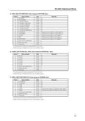
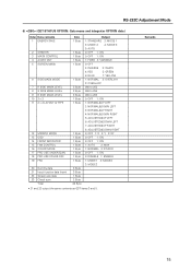
...3 4 5 6 7 8 9 10 11 12 13 14 15 16 Data contents CONTRAST BRIGHTNESS C. DETAIL Y (YELLOW) C. DETAIL M (MAGENTA) H.ENHANCE V.ENHANCE COLOR TINT SHARPNESS Input function data (main) Screen size data Check sum Size 3 Byte 3 Byte 3 Byte 3 Byte 3 Byte 3 Byte 3 Byte 3 Byte 3 Byte 3 Byte 3 Byte 3 Byte...output. Remarks 4) (GET POSITION DATA: Gets integrator/SCREEN data.) Order 1 2 3 4 5 6 7 8 9 Data contents H.POSITION V.POSITION H.SIZE V.SIZE CLOCK PHASE Input function data (main) Screen size data Check sum Size 3 Byte 3 Byte 3 Byte 3 Byte 3 Byte 3 Byte 3 Byte 1 Byte 2 Byte Remarks # # #...
...3 4 5 6 7 8 9 10 11 12 13 14 15 16 Data contents CONTRAST BRIGHTNESS C. DETAIL Y (YELLOW) C. DETAIL M (MAGENTA) H.ENHANCE V.ENHANCE COLOR TINT SHARPNESS Input function data (main) Screen size data Check sum Size 3 Byte 3 Byte 3 Byte 3 Byte 3 Byte 3 Byte 3 Byte 3 Byte 3 Byte 3 Byte 3 Byte 3 Byte...output. Remarks 4) (GET POSITION DATA: Gets integrator/SCREEN data.) Order 1 2 3 4 5 6 7 8 9 Data contents H.POSITION V.POSITION H.SIZE V.SIZE CLOCK PHASE Input function data (main) Screen size data Check sum Size 3 Byte 3 Byte 3 Byte 3 Byte 3 Byte 3 Byte 3 Byte 1 Byte 2 Byte Remarks # # #...

Command Reference
Page 14
... contents 1 GRADATION 2 BRT.ENHANCE 3 SUB VOLUME 4 COLOR TEMP. 5 DNR 6 MPEG NR 7 CTI 8 PURECINEMA 9 COLOR DECODING 10 COLOR SYSTEM 11 SIGNAL FORMAT 12 Dummy data 13 Input function data (main) 14 Screen size data 15 Check sum Size 1 Byte 1 Byte 2 Byte 1 Byte 1 Byte 1 Byte 1 Byte 1 Byte 1 Byte 1 Byte 3 Byte 3 Byte 3 Byte 1 Byte...
... contents 1 GRADATION 2 BRT.ENHANCE 3 SUB VOLUME 4 COLOR TEMP. 5 DNR 6 MPEG NR 7 CTI 8 PURECINEMA 9 COLOR DECODING 10 COLOR SYSTEM 11 SIGNAL FORMAT 12 Dummy data 13 Input function data (main) 14 Screen size data 15 Check sum Size 1 Byte 1 Byte 2 Byte 1 Byte 1 Byte 1 Byte 1 Byte 1 Byte 1 Byte 1 Byte 3 Byte 3 Byte 3 Byte 1 Byte...
Command Reference
Page 15
... OSD 14 FRONT INDICATOR 15 FAN CONTROL 16 COLOR MODE 17 PRO USE UNDERSCAN 18 PRO USE COLOR OFF 19 FRC 20 Dummy data 21 Input function data (main) 22 Screen size data 23 Check sum Total Size 1 Byte 1 Byte 1 Byte 1 Byte 1 Byte 1 Byte 3 Byte 3 Byte 3 Byte 1 Byte 1 Byte 1 Byte 1 Byte...
... OSD 14 FRONT INDICATOR 15 FAN CONTROL 16 COLOR MODE 17 PRO USE UNDERSCAN 18 PRO USE COLOR OFF 19 FRC 20 Dummy data 21 Input function data (main) 22 Screen size data 23 Check sum Total Size 1 Byte 1 Byte 1 Byte 1 Byte 1 Byte 1 Byte 3 Byte 3 Byte 3 Byte 1 Byte 1 Byte 1 Byte 1 Byte...
Command Reference
Page 17
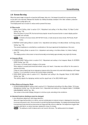
... is not possible to remove the burned image completely. 2 SIDE MASK Setting (refer to protect the plasma panel display. The setting cannot be an emergency measure when the screen is burned while displaying a still image; Screen Burning 2.0 Screen Burning When the same image is shown for a long time...the Menu Mode; 14) Orbiter Setting" (pg. 174). This display panel has a function to reduce and/or prevent this situation by a combination of the input signal and the brightness of the screen display changes on the screen. The display position of the SIDE MASK signal . 7 Menu Mode and ...
... is not possible to remove the burned image completely. 2 SIDE MASK Setting (refer to protect the plasma panel display. The setting cannot be an emergency measure when the screen is burned while displaying a still image; Screen Burning 2.0 Screen Burning When the same image is shown for a long time...the Menu Mode; 14) Orbiter Setting" (pg. 174). This display panel has a function to reduce and/or prevent this situation by a combination of the input signal and the brightness of the screen display changes on the screen. The display position of the SIDE MASK signal . 7 Menu Mode and ...

Command Reference
Page 19
...reading the contents of the error message, refer to no motion such as the temperature increases; Check the table of supported input signals on the plasma display then wait 1 to no motion then automatically adjusts the brightness. Immediately turn the power ON again. Turn OFF the main ...persists, remove the power plug from the outlet and contact a Pioneer service center or dealer. 19 The fan's rpm becomes faster as a photograph or PC screen is displayed continuously, the brightness slightly drops. To protect the plasma panel, the screen-saver function detects images with a sync ...
...reading the contents of the error message, refer to no motion such as the temperature increases; Check the table of supported input signals on the plasma display then wait 1 to no motion then automatically adjusts the brightness. Immediately turn the power ON again. Turn OFF the main ...persists, remove the power plug from the outlet and contact a Pioneer service center or dealer. 19 The fan's rpm becomes faster as a photograph or PC screen is displayed continuously, the brightness slightly drops. To protect the plasma panel, the screen-saver function detects images with a sync ...

