
English Manual
Page 2
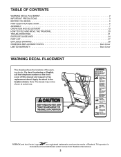
... manual and request a free replacement decal. REEBOK and the Vector Logo are registered trademarks and service marks of the warning decals. TABLE OF CONTENTS WARNING DECAL PLACEMENT 2 IMPORTANT PRECAUTIONS 3 BEFORE YOU BEGIN 5 PART IDENTIFICATION CHART 6 ASSEMBLY 7 OPERATION AND ADJUSTMENT 13 HOW TO FOLD AND MOVE THE TREADMILL 20 TROUBLESHOOTING 21 EXERCISE GUIDELINES 24...
... manual and request a free replacement decal. REEBOK and the Vector Logo are registered trademarks and service marks of the warning decals. TABLE OF CONTENTS WARNING DECAL PLACEMENT 2 IMPORTANT PRECAUTIONS 3 BEFORE YOU BEGIN 5 PART IDENTIFICATION CHART 6 ASSEMBLY 7 OPERATION AND ADJUSTMENT 13 HOW TO FOLD AND MOVE THE TREADMILL 20 TROUBLESHOOTING 21 EXERCISE GUIDELINES 24...
English Manual
Page 4
...treadmill unattended while it is properly assembled. (See ASSEMBLY on page 7, and HOW TO FOLD AND MOVE THE TREADMILL on page 20.) You must be performed by an authorized service representative. Do not use only. DANGER: 25. Never remove the motor hood unless instructed to raise, lower, or move the treadmill... switch into any object into the off position when the treadmill is intended for the location of the treadmill regularly. ing the treadmill, and before clean- When folding or moving the treadmill, make sure that the storage latch is running. Always unplug...
...treadmill unattended while it is properly assembled. (See ASSEMBLY on page 7, and HOW TO FOLD AND MOVE THE TREADMILL on page 20.) You must be performed by an authorized service representative. Do not use only. DANGER: 25. Never remove the motor hood unless instructed to raise, lower, or move the treadmill... switch into any object into the off position when the treadmill is intended for the location of the treadmill regularly. ing the treadmill, and before clean- When folding or moving the treadmill, make sure that the storage latch is running. Always unplug...
English Manual
Page 6
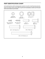
... (12)—-1 3/8" x 2" Bolt (13)—-1 3/8" x 3 1/2" Screw (4)—-6 6 The number following the key number is the quantity used for assembly. The number in the hardware kit, check to identify small parts used for assembly. PART IDENTIFICATION CHART Use the drawings below each drawing is the key number of the part, from the PART...
... (12)—-1 3/8" x 2" Bolt (13)—-1 3/8" x 3 1/2" Screw (4)—-6 6 The number following the key number is the quantity used for assembly. The number in the hardware kit, check to identify small parts used for assembly. PART IDENTIFICATION CHART Use the drawings below each drawing is the key number of the part, from the PART...
English Manual
Page 7
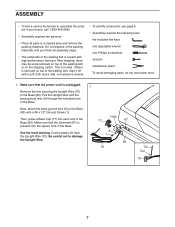
...Grommet (67) is coated with a soft cloth and a mild, non-abrasive cleaner. •• To identify small parts, see page 6. •• Assembly requires the following tools: the included hex keys one adjustable wrench one Phillips screwdriver scissors needlenose pliers To avoid damaging parts, do not use power... tools. 1. Cut the plastic tie near the Upright Wire (70). Hole 77 67 A 1 80 70 Tie Cut 70 7 ASSEMBLY •• To hire a service technician to damage the Upright Wire. After shipping, there may be some lubricant on top of the Base (80)....
...Grommet (67) is coated with a soft cloth and a mild, non-abrasive cleaner. •• To identify small parts, see page 6. •• Assembly requires the following tools: the included hex keys one adjustable wrench one Phillips screwdriver scissors needlenose pliers To avoid damaging parts, do not use power... tools. 1. Cut the plastic tie near the Upright Wire (70). Hole 77 67 A 1 80 70 Tie Cut 70 7 ASSEMBLY •• To hire a service technician to damage the Upright Wire. After shipping, there may be some lubricant on top of the Base (80)....
English Manual
Page 10
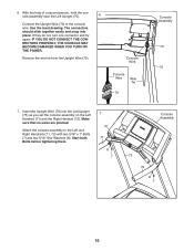
... tie from the Upright Wire (70). Make sure that no wires are pinched. Attach the console assembly to the console wire. See the inset drawing. IF YOU DO NOT CONNECT THE CONNECTORS PROPERLY, ... together easily and snap into the Left Upright (75) as you set the console assembly on the Left Handrail (71) and the Right Handrail (72). With the help of a second person, hold the ...console assembly near the Left Upright (75). 6 Connect the Upright Wire (70) to the Left and Right Handrails (71, 72) ...
... tie from the Upright Wire (70). Make sure that no wires are pinched. Attach the console assembly to the console wire. See the inset drawing. IF YOU DO NOT CONNECT THE CONNECTORS PROPERLY, ... together easily and snap into the Left Upright (75) as you set the console assembly on the Left Handrail (71) and the Right Handrail (72). With the help of a second person, hold the ...console assembly near the Left Upright (75). 6 Connect the Upright Wire (70) to the Left and Right Handrails (71, 72) ...
English Manual
Page 11
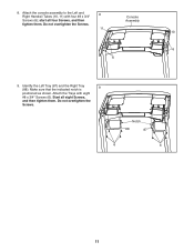
Console Assembly 11 10 6 6 9. Notch 88 87 6 6 11 start all eight Screws, and then tighten them . Attach the Trays with four #8 x 3/4" 8 Screws (6); Start all four Screws, and then tighten them . Do not overtighten the Screws. Identify the Left Tray (87) and the Right Tray (88). Do not overtighten the Screws. Make sure that the indicated notch is 9 positioned as shown. 8. Attach the console assembly to the Left and Right Handrail Tubes (10, 11) with eight #8 x 3/4" Screws (6).
Console Assembly 11 10 6 6 9. Notch 88 87 6 6 11 start all eight Screws, and then tighten them . Attach the Trays with four #8 x 3/4" 8 Screws (6); Start all four Screws, and then tighten them . Do not overtighten the Screws. Identify the Left Tray (87) and the Right Tray (88). Do not overtighten the Screws. Make sure that the indicated notch is 9 positioned as shown. 8. Attach the console assembly to the Left and Right Handrail Tubes (10, 11) with eight #8 x 3/4" Screws (6).