

Owners Manual
Page 4
...performing any part of your tool to a workbench or table at a time. Always feed workpiece from left to right against the direction the drum sleeve is sufficient to inflict severe injury. make sure the work area has ample lighting to see the work and that no debris between worktable... IF SWITCH DOES NOT TURN IT ON AND OFF. ALWAYS REMEMBER that a careless fraction of a second is rotating. Do not use drums, sanding sleeves or belts which show visual signs of wear such as those dust masks that are specially designed to instruct others who may use a clean cloth...
...performing any part of your tool to a workbench or table at a time. Always feed workpiece from left to right against the direction the drum sleeve is sufficient to inflict severe injury. make sure the work area has ample lighting to see the work and that no debris between worktable... IF SWITCH DOES NOT TURN IT ON AND OFF. ALWAYS REMEMBER that a careless fraction of a second is rotating. Do not use drums, sanding sleeves or belts which show visual signs of wear such as those dust masks that are specially designed to instruct others who may use a clean cloth...
Owners Manual
Page 9
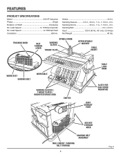
... Weight 40 lbs. Sanding Drums 3/4 in., 1 in., 1-1/2 in., 2 in . tracking knob belt tension lever spindle knob sanding sleeve REMOVE Throat plate upper spindle washer table insert REMOVE work rest sanding belt worktable aaaa sanding sleeves / Throat plates / washer storage area switch table lock knob slots for saw horse mounting dust exhaust port... Motor 3/8 HP Induction Phase Single Rotation of Shaft Clockwise No Load Speed 0-1725/rpm/spindle No Load Speed 0-1350/rpm/belt Oscillation 60/min. Sanding Sleeves ......... 1/2 in., 3/4 in., 1 in., 1-1/2 in., 2 in.
... Weight 40 lbs. Sanding Drums 3/4 in., 1 in., 1-1/2 in., 2 in . tracking knob belt tension lever spindle knob sanding sleeve REMOVE Throat plate upper spindle washer table insert REMOVE work rest sanding belt worktable aaaa sanding sleeves / Throat plates / washer storage area switch table lock knob slots for saw horse mounting dust exhaust port... Motor 3/8 HP Induction Phase Single Rotation of Shaft Clockwise No Load Speed 0-1725/rpm/spindle No Load Speed 0-1350/rpm/belt Oscillation 60/min. Sanding Sleeves ......... 1/2 in., 3/4 in., 1 in., 1-1/2 in., 2 in.
Owners Manual
Page 10
... hook-up. Belt Tension Lever Slide lever left hand threads. Tracking Knob Turning knob counterclockwise causes sanding belt to spindle sanding (or belt sanding). Sanding Sleeve/Drum Removes material from wood. Dust exhaust Port 2-1/2 in .) up and down to use this product, familiarize yourself with a sturdy, worktable that provides a stable surface...
... hook-up. Belt Tension Lever Slide lever left hand threads. Tracking Knob Turning knob counterclockwise causes sanding belt to spindle sanding (or belt sanding). Sanding Sleeve/Drum Removes material from wood. Dust exhaust Port 2-1/2 in .) up and down to use this product, familiarize yourself with a sturdy, worktable that provides a stable surface...

Owners Manual
Page 11
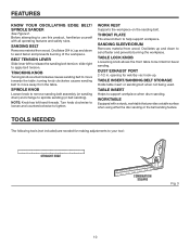
...use of attachments or accessories not listed might be hazardous and could cause serious personal injury. O.D. 7/8 in . I .D. Sanding Sleeves (5) Sanding Drums (4) Sanding Belt Assembly Table Insert Operator's Manual RUBBER FEET HEX KEYS 1-3/4 in...; Hex Keys (2) Knob Rubber Feet (4) Throat plates SWITCH KEY Flat Washers (4),1-3/4 in. WASHER WASHER WASHER WASHER SANDING SLEEVES TABLE INSERT KNOB SANDING DRUMS SANDING BELT ASSEMBLY 1/2 in. 3/4 in. 1 in. 1-1/2 in. 2 in . O.D., 5/8 in a hazardous condition ...
...use of attachments or accessories not listed might be hazardous and could cause serious personal injury. O.D. 7/8 in . I .D. Sanding Sleeves (5) Sanding Drums (4) Sanding Belt Assembly Table Insert Operator's Manual RUBBER FEET HEX KEYS 1-3/4 in...; Hex Keys (2) Knob Rubber Feet (4) Throat plates SWITCH KEY Flat Washers (4),1-3/4 in. WASHER WASHER WASHER WASHER SANDING SLEEVES TABLE INSERT KNOB SANDING DRUMS SANDING BELT ASSEMBLY 1/2 in. 3/4 in. 1 in. 1-1/2 in. 2 in . O.D., 5/8 in a hazardous condition ...
Owners Manual
Page 13
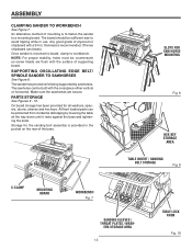
...countersunk so screw heads are secure. On board storage has been provided for being supported by lowering the table all washers, spacers, drums, sleeves and hex keys. All front loaded parts can break.) Once sander is recommended. (Thinner chipboard can be sufficient size to workbench. The ... mounting Fig. 8 hex key storage area REMOVE table insert / sanding belt storage Fig. 9 C-CLAMP MOUNTING BOARD WORKBENCH aaaa Fig. 7 sanding sleeves / Throat plates / wash- REMOVE REMOVE slots for the sanding belt assembly is to fasten the sander to Sawhorses See Figure 8.
...countersunk so screw heads are secure. On board storage has been provided for being supported by lowering the table all washers, spacers, drums, sleeves and hex keys. All front loaded parts can break.) Once sander is recommended. (Thinner chipboard can be sufficient size to workbench. The ... mounting Fig. 8 hex key storage area REMOVE table insert / sanding belt storage Fig. 9 C-CLAMP MOUNTING BOARD WORKBENCH aaaa Fig. 7 sanding sleeves / Throat plates / wash- REMOVE REMOVE slots for the sanding belt assembly is to fasten the sander to Sawhorses See Figure 8.

Owners Manual
Page 15
.... n Plug power cord in the table recess. (See recommended throat plate insert selection area from inside table recess. n Slide the sanding sleeve-rubber drum onto the spindle. Use the smallest throat plate insert that will fit over the fan. n Place desired sanding.... The fan is difficult to slide over the spindle, apply talcum powder to tighten. NOTE: Knob turns counterclockwise to the spindle. HEX KEY KNOB SANDING SLEEVE SANDING DRUM Fig. 13 REMOVE WASHER Throat plate Fig. 14 15° 30° 45° 0° 1/2 3/4 1 11/2 P 2 U L ON LI P U S H OFF O...
.... n Plug power cord in the table recess. (See recommended throat plate insert selection area from inside table recess. n Slide the sanding sleeve-rubber drum onto the spindle. Use the smallest throat plate insert that will fit over the fan. n Place desired sanding.... The fan is difficult to slide over the spindle, apply talcum powder to tighten. NOTE: Knob turns counterclockwise to the spindle. HEX KEY KNOB SANDING SLEEVE SANDING DRUM Fig. 13 REMOVE WASHER Throat plate Fig. 14 15° 30° 45° 0° 1/2 3/4 1 11/2 P 2 U L ON LI P U S H OFF O...

Owners Manual
Page 16
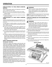
...in . O.D. 1/2 in . Throat plate 1-11/16 in . Throat plate Fig. 16 16 NOTE: Use the largest upper spindle washer that will not protrude past sanding sleeve. I .D. Sanding Sleeve Diameter 1/2 in. 3/4 in. 1 in. 1-1/2 in. 2 in . n Locate 1/2 in . WASHER 15/16 in . throat plate into the power source and... the yellow switch key. I .D. Throat plate 2-3/16 in . n Remove the fan and clean sawdust from inside table recess. sanding sleeve and slide it on the spindle. (Rubber drum is used .) n Install the upper spindle washer and tighten the knob. ASSEMBLY Installing Sanding...
...in . O.D. 1/2 in . Throat plate 1-11/16 in . Throat plate Fig. 16 16 NOTE: Use the largest upper spindle washer that will not protrude past sanding sleeve. I .D. Sanding Sleeve Diameter 1/2 in. 3/4 in. 1 in. 1-1/2 in. 2 in . n Locate 1/2 in . WASHER 15/16 in . throat plate into the power source and... the yellow switch key. I .D. Throat plate 2-3/16 in . n Remove the fan and clean sawdust from inside table recess. sanding sleeve and slide it on the spindle. (Rubber drum is used .) n Install the upper spindle washer and tighten the knob. ASSEMBLY Installing Sanding...

Owners Manual
Page 17
...WHEN SANDER IS RUNNING Before starting when power returns. n Wait for all moving parts to make sure the belt or drum and sleeve are properly installed. Remember that a careless fraction of a power failure, turn oFF rEMOVE switch key WARNING: Always remove the switch..., hold switch in with other hand. CAUTION: Before turning switch on edges, faces, contours, inside and outside curves. Press workpiece against the sanding sleeve or belt hard enough to a complete stop. for the purposes listed below: Oscillating and Rotary Motion - BEFORE LEAVING THE SANDER n Turn...
...WHEN SANDER IS RUNNING Before starting when power returns. n Wait for all moving parts to make sure the belt or drum and sleeve are properly installed. Remember that a careless fraction of a power failure, turn oFF rEMOVE switch key WARNING: Always remove the switch..., hold switch in with other hand. CAUTION: Before turning switch on edges, faces, contours, inside and outside curves. Press workpiece against the sanding sleeve or belt hard enough to a complete stop. for the purposes listed below: Oscillating and Rotary Motion - BEFORE LEAVING THE SANDER n Turn...
Owners Manual
Page 18
... paint particles: Do not eat, drink, or smoke in a work evenly across the sanding belt. Select and install the desired sanding sleeve for power sanding. to the workpiece you are best for the particular application. can be sanded will determine which grit will do not offer...the workpiece being sanded. Natural abrasives, such as flint and garnet, are available in . If the surface is rough, start with its matching sanding sleeve could cause a fire. Wear a dust mask or respirator at all paints: n Protect your lungs. Always continue sanding with both hands, keeping ...
... paint particles: Do not eat, drink, or smoke in a work evenly across the sanding belt. Select and install the desired sanding sleeve for power sanding. to the workpiece you are best for the particular application. can be sanded will determine which grit will do not offer...the workpiece being sanded. Natural abrasives, such as flint and garnet, are available in . If the surface is rough, start with its matching sanding sleeve could cause a fire. Wear a dust mask or respirator at all paints: n Protect your lungs. Always continue sanding with both hands, keeping ...

Owners Manual
Page 19
...idler drum end of workpiece or possible injury. The idler drum is not recommended. Feed Direction See Figure 21. Feed the workpiece against the sanding sleeve from left to sand curves may be sanded on the drive drum when in the opposite direction, the rotation forces of the belt tracking mechanism... curved edge sanding REMOVE Fig. 19 Fig. 20 REMOVE feed direction Fig. 21 19 Although it is an integral part of the spinning sanding sleeve will tend to throw or bounce the workpiece away from left to right, the rotation of the idler drum to right as shown. When fed...
...idler drum end of workpiece or possible injury. The idler drum is not recommended. Feed Direction See Figure 21. Feed the workpiece against the sanding sleeve from left to sand curves may be sanded on the drive drum when in the opposite direction, the rotation forces of the belt tracking mechanism... curved edge sanding REMOVE Fig. 19 Fig. 20 REMOVE feed direction Fig. 21 19 Although it is an integral part of the spinning sanding sleeve will tend to throw or bounce the workpiece away from left to right, the rotation of the idler drum to right as shown. When fed...

Owners Manual
Page 23
... local Home Depot store. replacement sanding belts are available at Home Depot stores: Miter Gauge AC1021 Switch Key AC1000 Universal Legset AC9910 Replacement Sanding Sleeves, 2 pk.
... local Home Depot store. replacement sanding belts are available at Home Depot stores: Miter Gauge AC1021 Switch Key AC1000 Universal Legset AC9910 Replacement Sanding Sleeves, 2 pk.