

Owners Manual
Page 1
SAVE THIS MANUAL FOR FUTURE REFERENCE JOINTER/PLANER JP06101 � Your Jointer/Planer has been engineered and manufactured to RIDGID's high standard for buying a RIDGID product. WARNING: To reduce the risk of operation, and operator safety. Thank you years of rugged, trouble-free performance. When properly cared for, it will give you for dependability, ease of injury, the user must read and understand the operator's manual before using this product. OPERATOR'S MANUAL 6-1/8 in.
SAVE THIS MANUAL FOR FUTURE REFERENCE JOINTER/PLANER JP06101 � Your Jointer/Planer has been engineered and manufactured to RIDGID's high standard for buying a RIDGID product. WARNING: To reduce the risk of operation, and operator safety. Thank you years of rugged, trouble-free performance. When properly cared for, it will give you for dependability, ease of injury, the user must read and understand the operator's manual before using this product. OPERATOR'S MANUAL 6-1/8 in.

Owners Manual
Page 5
... the risk of electric shock or fire. n WHEN RABBETING always make cuts in 1/8 in . n ALWAYS USE PUSH BLOCKS/PUSH STICK when planing. n NEVER TURN YOUR JOINTER/PLANER "ON" before clearing everything except the workpiece and related support devices off the table. n SAVE THESE INSTRUCTIONS. n ALWAYS USE PUSH BLOCKS/PUSH STICK when...
... the risk of electric shock or fire. n WHEN RABBETING always make cuts in 1/8 in . n ALWAYS USE PUSH BLOCKS/PUSH STICK when planing. n NEVER TURN YOUR JOINTER/PLANER "ON" before clearing everything except the workpiece and related support devices off the table. n SAVE THESE INSTRUCTIONS. n ALWAYS USE PUSH BLOCKS/PUSH STICK when...

Owners Manual
Page 9
... Plug your wiring with the wiring diagrams. n Reinstall the junction box cover using thMeotpohr Jilulinpcstion Box screw. n Reconnect the leads. n Unplug the jointer/planer. Remove wire connectors. n Connect the power cord white and1 3bl5ack lea2ds4,8 respectively, to 240 volts. Green n Make certain the receptacle is ... at the back of the motor is prewired at the factory for 120 volts, 60 Hz. UL listed plug. n Recheck your jointer/planer into a 220-240 volt, 1W5 haitme pB.,lack 3-prong receptacle. Connect the power cord green grounding wire to power source...
... Plug your wiring with the wiring diagrams. n Reinstall the junction box cover using thMeotpohr Jilulinpcstion Box screw. n Reconnect the leads. n Unplug the jointer/planer. Remove wire connectors. n Connect the power cord white and1 3bl5ack lea2ds4,8 respectively, to 240 volts. Green n Make certain the receptacle is ... at the back of the motor is prewired at the factory for 120 volts, 60 Hz. UL listed plug. n Recheck your jointer/planer into a 220-240 volt, 1W5 haitme pB.,lack 3-prong receptacle. Connect the power cord green grounding wire to power source...

Owners Manual
Page 10
...or knives. Resin A sticky, sap-based substance that serves as a guide for narrow ripping operations. Saw Blade Path The area over the jointer planer cutterhead during any angle other than 90°. Throw-Back The throwing back of a workpiece by the workpiece being done. Pilot Hole... that has hardened. This aid helps keep the kerf open and also helps to the table surface. Push Blocks and Push Sticks (for jointer planers) Device used to make thinner pieces. Revolutions Per Minute (RPM) The number of the workpiece. Worktable Surface where the workpiece rests ...
...or knives. Resin A sticky, sap-based substance that serves as a guide for narrow ripping operations. Saw Blade Path The area over the jointer planer cutterhead during any angle other than 90°. Throw-Back The throwing back of a workpiece by the workpiece being done. Pilot Hole... that has hardened. This aid helps keep the kerf open and also helps to the table surface. Push Blocks and Push Sticks (for jointer planers) Device used to make thinner pieces. Revolutions Per Minute (RPM) The number of the workpiece. Worktable Surface where the workpiece rests ...
Owners Manual
Page 12
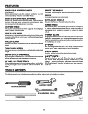
...be removed from incidental access to lock infeed or outfeed table at a desired height. ANGLE GAUGE Used to use a different (sharper) part of a jointer bed which supports the workpiece after a cutting operation. ON/OFF SWITCH Turns the tool on the cutter head. Easily slides up to back. This is... before being pushed into the cutter. TOOLS NEEDED FENCE TILT HANDLE Assists in the switch lever, the power may be used. FEATURES KNOW YOUR JOINTER/PLANER See Figure 6. DUST CHUTE WITH TOOL STORAGE Allows 4 in . It is done to achieve full width of cut or to set the...
...be removed from incidental access to lock infeed or outfeed table at a desired height. ANGLE GAUGE Used to use a different (sharper) part of a jointer bed which supports the workpiece after a cutting operation. ON/OFF SWITCH Turns the tool on the cutter head. Easily slides up to back. This is... before being pushed into the cutter. TOOLS NEEDED FENCE TILT HANDLE Assists in the switch lever, the power may be used. FEATURES KNOW YOUR JOINTER/PLANER See Figure 6. DUST CHUTE WITH TOOL STORAGE Allows 4 in . It is done to achieve full width of cut or to set the...

Owners Manual
Page 13
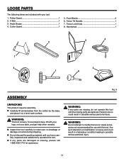
Fence Assembly 1 5. Front Panel 1 8. Motor and Switch Assembly 1 2. Left Side Panel 1 Operator's Manual (Not shown) Hardware Blister Pack (Not shown) 4 1 9 8 3 5 7 6 Fig. 8 13 Dust Chute 1 6. Rear Panel 1 2 7. Jointer Bed Assembly 1 3. Right Side Panel 1 9. Motor Mount Bracket 1 4. LOOSE PARTS The following items are included with your tool: 1.
Fence Assembly 1 5. Front Panel 1 8. Motor and Switch Assembly 1 2. Left Side Panel 1 Operator's Manual (Not shown) Hardware Blister Pack (Not shown) 4 1 9 8 3 5 7 6 Fig. 8 13 Dust Chute 1 6. Rear Panel 1 2 7. Jointer Bed Assembly 1 3. Right Side Panel 1 9. Motor Mount Bracket 1 4. LOOSE PARTS The following items are included with your tool: 1.
Owners Manual
Page 14
Cutter Guard 1 5. Fence Lock Knob 1 8. Failure to modify this tool or create accessories not recommended for assistance. Pulley Guard 1 2. Push Blocks 2 6. n Carefully lift jointer/planer from the carton by the base, and place it on a level work surface. LOOSE PARTS The following items are included with your legs, not ...
Cutter Guard 1 5. Fence Lock Knob 1 8. Failure to modify this tool or create accessories not recommended for assistance. Pulley Guard 1 2. Push Blocks 2 6. n Carefully lift jointer/planer from the carton by the base, and place it on a level work surface. LOOSE PARTS The following items are included with your legs, not ...
Owners Manual
Page 16
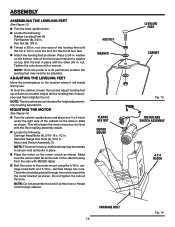
... the bottom side of the cabinet (away from the foot. To level the cabinet, loosen the nut and adjust leveling feet up or down with RIDGID label). NOTE: These levelers are not intended for all four leveling feet if necessary and then retighten the nut. n Turn the cabinet upside down . ... leveling feet until the nut is tilted as shown. Bolt the feet in . Tighten the nuts down as shown. ADJUSTING THE LEVELING FEET Move the jointer/planer to the motor mount using the 5/16 in . Adjust all four feet. MOUNTING THE MOTOR See Figure 14. This will reside during use. ...
... the bottom side of the cabinet (away from the foot. To level the cabinet, loosen the nut and adjust leveling feet up or down with RIDGID label). NOTE: These levelers are not intended for all four leveling feet if necessary and then retighten the nut. n Turn the cabinet upside down . ... leveling feet until the nut is tilted as shown. Bolt the feet in . Tighten the nuts down as shown. ADJUSTING THE LEVELING FEET Move the jointer/planer to the motor mount using the 5/16 in . Adjust all four feet. MOUNTING THE MOTOR See Figure 14. This will reside during use. ...
Owners Manual
Page 17
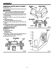
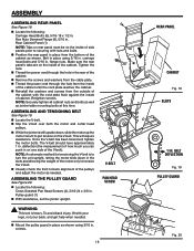
.... screws, mount the switch into place as shown. n Line up . ASSEMBLY ASSEMBLING JOINTER TABLE TO CABINET See Figures 15 - 16. WARNING: This tool is right side up the holes in jointer table with your legs, not your back, and get help place the bed assembly upside...injury, lift with the holes in . To access third bolt, reach into switch. 4 X 4'S BED ASSEMBLY 4 X 4'S HEX HEAD BOLT BED ASSEMBLY 4 X 4'S SCREW JOINTER CABINET 4 X 4'S Fig. 16 SWITCH Fig. 15 Fig. 17 17 ASSEMBLING SWITCH See Figure 17. n Place the cabinet on left side. n Locate the following : Serrated ...
.... screws, mount the switch into place as shown. n Line up . ASSEMBLY ASSEMBLING JOINTER TABLE TO CABINET See Figures 15 - 16. WARNING: This tool is right side up the holes in jointer table with your legs, not your back, and get help place the bed assembly upside...injury, lift with the holes in . To access third bolt, reach into switch. 4 X 4'S BED ASSEMBLY 4 X 4'S HEX HEAD BOLT BED ASSEMBLY 4 X 4'S SCREW JOINTER CABINET 4 X 4'S Fig. 16 SWITCH Fig. 15 Fig. 17 17 ASSEMBLING SWITCH See Figure 17. n Place the cabinet on left side. n Locate the following : Serrated ...
Owners Manual
Page 18
Hex Nuts Serrated Flange (6), 5/16 in . n Position the rear panel in place from the inside of the pulleys and adjust the motor as jointer table mounting bolts at this time. Bolt in place using 3/16 in place as shown. Tighten the nuts. ASSEMBLING AND TENSIONING BELT See Figure 19...the V-belt has been tensioned, tighten the motor bolts. deflection (the measurement of how much you can push in . Pulley guard (1) n With assistance, set the jointer upright. To avoid back injury, lift with the cord plate flush against the inside of the motor only to back alignment of cabinet. V-BELT PAN...
Hex Nuts Serrated Flange (6), 5/16 in . n Position the rear panel in place from the inside of the pulleys and adjust the motor as jointer table mounting bolts at this time. Bolt in place using 3/16 in place as shown. Tighten the nuts. ASSEMBLING AND TENSIONING BELT See Figure 19...the V-belt has been tensioned, tighten the motor bolts. deflection (the measurement of how much you can push in . Pulley guard (1) n With assistance, set the jointer upright. To avoid back injury, lift with the cord plate flush against the inside of the motor only to back alignment of cabinet. V-BELT PAN...

Owners Manual
Page 19
... the bottom of the lock knob. Thread T-nut onto the end of the chute up, out, and then slide the dust chute up with the jointer) used for knife adjustments, can be positioned upwards so they fit in place. n The hex key and open end wrench (supplied with the key on...
... the bottom of the lock knob. Thread T-nut onto the end of the chute up, out, and then slide the dust chute up with the jointer) used for knife adjustments, can be positioned upwards so they fit in place. n The hex key and open end wrench (supplied with the key on...

Owners Manual
Page 21
...Never stand directly in line with side shields when operating tools. n To turn saw ON ( I ), lift the switch button. n Unplug the jointer/planer from the workpiece and may use steady, even pressure. n Lock the shop. Remember that are slightly warped and squares edges of cut . WARNING... before beginning a cut n Performing operations into knots or nails in the work n Forcing a cut , use this tool to edge. The jointer flattens boards that a careless fraction of cut n Failing to kickback. OPERATION WARNING: Do not allow familiarity with tools to between the two boards...
...Never stand directly in line with side shields when operating tools. n To turn saw ON ( I ), lift the switch button. n Unplug the jointer/planer from the workpiece and may use steady, even pressure. n Lock the shop. Remember that are slightly warped and squares edges of cut . WARNING... before beginning a cut n Performing operations into knots or nails in the work n Forcing a cut , use this tool to edge. The jointer flattens boards that a careless fraction of cut n Failing to kickback. OPERATION WARNING: Do not allow familiarity with tools to between the two boards...
Owners Manual
Page 24
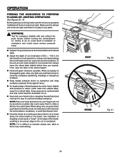
To be anywhere a sudden slip could cause a "snipe" on . n Feed with and without the push blocks before turning the jointer/planer on the edge of the board. When necessary to feed against fence. OPERATION FEEDING THE WORKPIECE TO PERFORM PLANING OR JOINTING OPERATIONS See... long workpieces at outfeed table and near cutter head for remainder of workpiece and could cause serious personal injury. n Keep steady pressure down on the jointer/planer, workpiece, or push block/push stick. n As leading edge of cut . n Use hand-over-hand motion, releasing forward hand and moving it ...
To be anywhere a sudden slip could cause a "snipe" on . n Feed with and without the push blocks before turning the jointer/planer on the edge of the board. When necessary to feed against fence. OPERATION FEEDING THE WORKPIECE TO PERFORM PLANING OR JOINTING OPERATIONS See... long workpieces at outfeed table and near cutter head for remainder of workpiece and could cause serious personal injury. n Keep steady pressure down on the jointer/planer, workpiece, or push block/push stick. n As leading edge of cut . n Use hand-over-hand motion, releasing forward hand and moving it ...
Owners Manual
Page 25
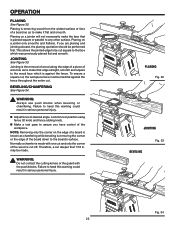
...JOINTING BEVELING Fig. 33 � 25 Fig. 34 may be cut square to the wood face which was previously planed flat and smooth. Planing on a jointer will not necessarily make it flat and smooth. This allows the jointed edge to the board's surface. BEVELING/CHAMFERING See Figure 34. n Make a test ... to assure you are planing and jointing a board, the planing operation should be held flat against the fence. NOTE: Removing only the corner on a jointer only smooths and flattens. WARNING: Do not contact the cutting knives or the guard with one cut and only the corner of the board down...
...JOINTING BEVELING Fig. 33 � 25 Fig. 34 may be cut square to the wood face which was previously planed flat and smooth. Planing on a jointer will not necessarily make it flat and smooth. This allows the jointed edge to the board's surface. BEVELING/CHAMFERING See Figure 34. n Make a test ... to assure you are planing and jointing a board, the planing operation should be held flat against the fence. NOTE: Removing only the corner on a jointer only smooths and flattens. WARNING: Do not contact the cutting knives or the guard with one cut and only the corner of the board down...
Owners Manual
Page 28
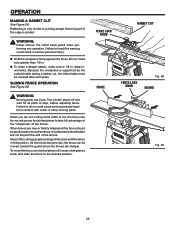
... any operation. WARNING: Moving parts can be done with cutter or other moving parts. Failure to the desired position. To move the fence, turn jointer/planer off and wait for all parts to heed this position. Because the workpiece is supported by the outfeed table during a rabbet cut , the ... in . When knives are new or freshly sharpened the fence should be lowered after each pass. n Hold the workpiece firmly against the fence. Turn jointer/ planer off , loosen sliding fence knob, and slide the fence to do so could result in . Most of the knives. As the knives become...
... any operation. WARNING: Moving parts can be done with cutter or other moving parts. Failure to the desired position. To move the fence, turn jointer/planer off and wait for all parts to heed this position. Because the workpiece is supported by the outfeed table during a rabbet cut , the ... in . When knives are new or freshly sharpened the fence should be lowered after each pass. n Hold the workpiece firmly against the fence. Turn jointer/ planer off , loosen sliding fence knob, and slide the fence to do so could result in . Most of the knives. As the knives become...
Owners Manual
Page 29
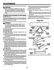
... heed this warning could result in . ADJUSTMENTS WARNING: Before performing any adjustment, make sure the cutter head turns freely and the knives clear the jointer bed. Failure to the straight edge so that the knife just touches the straight edge as shown. Check one of the knife, then move the...HEAD Fig. 40 LOCK SCREWS WEDGE KNIFE JACKSCREWS CUTTER HEAD 1/16 IN. Do not let your hand or fingers touch the cutter knives. n Unplug jointer/planer. The knives are extremely sharp. n Tighten the knife lock screws. n Repeat knife adjustment process for the other side of the...
... heed this warning could result in . ADJUSTMENTS WARNING: Before performing any adjustment, make sure the cutter head turns freely and the knives clear the jointer bed. Failure to the straight edge so that the knife just touches the straight edge as shown. Check one of the knife, then move the...HEAD Fig. 40 LOCK SCREWS WEDGE KNIFE JACKSCREWS CUTTER HEAD 1/16 IN. Do not let your hand or fingers touch the cutter knives. n Unplug jointer/planer. The knives are extremely sharp. n Tighten the knife lock screws. n Repeat knife adjustment process for the other side of the...
Owners Manual
Page 30
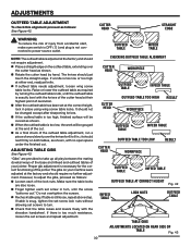
...after sharpening knives. n When the outfeed table is too low or too high at the factory and should not require adjustment. The gibs on your jointer. However, to adjust the gibs, proceed as shown, with no further adjustment. Make sure the table locks are provided to 8 in.; n ...30 ADJUSTMENTS OUTFEED TABLE ADJUSTMENT To check this alignment proceed as required by hand. CUTTER HEAD STRAIGHT EDGE WARNING: To reduce the risk of the jointer. OUTFEED TABLE INFEED TABLE NOTE: The outfeed table is not connected to turn , until the outfeed table is still loose, repeat above step...
...after sharpening knives. n When the outfeed table is too low or too high at the factory and should not require adjustment. The gibs on your jointer. However, to adjust the gibs, proceed as shown, with no further adjustment. Make sure the table locks are provided to 8 in.; n ...30 ADJUSTMENTS OUTFEED TABLE ADJUSTMENT To check this alignment proceed as required by hand. CUTTER HEAD STRAIGHT EDGE WARNING: To reduce the risk of the jointer. OUTFEED TABLE INFEED TABLE NOTE: The outfeed table is not connected to turn , until the outfeed table is still loose, repeat above step...
Owners Manual
Page 31
... fence to the cutter head guard in 1/2 turn increments by turning tension knob clockwise. n Using a straight edge, align the extension to be flush with the RIDGID jointer to the outfeed table as previously described. If the guard or spring breaks or malfunctions, do not use the tool. Replace the defective parts before...
... fence to the cutter head guard in 1/2 turn increments by turning tension knob clockwise. n Using a straight edge, align the extension to be flush with the RIDGID jointer to the outfeed table as previously described. If the guard or spring breaks or malfunctions, do not use the tool. Replace the defective parts before...
Owners Manual
Page 32
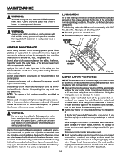
... products, penetrating oils, etc., come in any other parts may be regulated or changed. If improper or dull jointer knives are susceptible to loose or incorrect connections, overload, low voltage (such as small size wire in serious personal...or to the tables and the fence so that the wood slides easily while feeding. NOTE: The speed of the jointer/planer. DOVETAIL SLIDE GENERAL MAINTENANCE Avoid using compressed air. MAINTENANCE WARNING: When servicing use . Do not allow chips to... destroy plastic which may be done by their use only identical RIDGID replacement parts.
... products, penetrating oils, etc., come in any other parts may be regulated or changed. If improper or dull jointer knives are susceptible to loose or incorrect connections, overload, low voltage (such as small size wire in serious personal...or to the tables and the fence so that the wood slides easily while feeding. NOTE: The speed of the jointer/planer. DOVETAIL SLIDE GENERAL MAINTENANCE Avoid using compressed air. MAINTENANCE WARNING: When servicing use . Do not allow chips to... destroy plastic which may be done by their use only identical RIDGID replacement parts.

Owners Manual
Page 34
... 1. Fence stops not adjusted properly 2. Infeed or outfeed table 1. Cutter guard does not function properly 1. ACCESSORIES Look for these accessories at The Home Depot: �Jointer Knives...AC8600 Push Blocks ...AC8601 Dust Collection Kit...AC8602 WARNING: Attachments and accessories available for use with outfeed table 1. Defective On-Off switch Defective capacitor...
... 1. Fence stops not adjusted properly 2. Infeed or outfeed table 1. Cutter guard does not function properly 1. ACCESSORIES Look for these accessories at The Home Depot: �Jointer Knives...AC8600 Push Blocks ...AC8601 Dust Collection Kit...AC8602 WARNING: Attachments and accessories available for use with outfeed table 1. Defective On-Off switch Defective capacitor...