

Owners Manual
Page 13
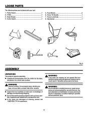
Motor and Switch Assembly 1 2. Right Side Panel 1 9. Front Panel 1 8. Motor Mount Bracket 1 4. Fence Assembly 1 5. Rear Panel 1 2 7. Left Side Panel 1 Operator's Manual (Not shown) Hardware Blister Pack (Not shown) 4 1 9 8 3 5 7 6 Fig. 8 13 Jointer Bed Assembly 1 3. Dust Chute 1 6. LOOSE PARTS The following items are included with your tool: 1.
Motor and Switch Assembly 1 2. Right Side Panel 1 9. Front Panel 1 8. Motor Mount Bracket 1 4. Fence Assembly 1 5. Rear Panel 1 2 7. Left Side Panel 1 Operator's Manual (Not shown) Hardware Blister Pack (Not shown) 4 1 9 8 3 5 7 6 Fig. 8 13 Jointer Bed Assembly 1 3. Dust Chute 1 6. LOOSE PARTS The following items are included with your tool: 1.
Owners Manual
Page 14
... If any parts are replaced. Fence Tilt Handle 1 7. WARNING: This tool is misuse and could result in a hazardous condition leading to modify this tool or create accessories not recommended for assistance. Handwheel 1 3 4 2 1 8 5 7 6 ASSEMBLY UNPACKING This product requires assembly. n If any parts are missing...Gauge 1 4. To avoid back injury, lift with this tool until you have carefully inspected and satisfactorily operated the tool. Fence Lock Knob 1 8. Failure to make sure no breakage or damage occurred during shipping. n Inspect the tool carefully to do...
... If any parts are replaced. Fence Tilt Handle 1 7. WARNING: This tool is misuse and could result in a hazardous condition leading to modify this tool or create accessories not recommended for assistance. Handwheel 1 3 4 2 1 8 5 7 6 ASSEMBLY UNPACKING This product requires assembly. n If any parts are missing...Gauge 1 4. To avoid back injury, lift with this tool until you have carefully inspected and satisfactorily operated the tool. Fence Lock Knob 1 8. Failure to make sure no breakage or damage occurred during shipping. n Inspect the tool carefully to do...

Owners Manual
Page 19
ELEVATION SHAFT DUST CHUTE ASSEMBLING FENCE ASSEMBLY TO BED ASSEMBLY See Figure 23. T-Nut (1) Fence Assembly (1) Fence Lock Knob (1) Fence Tilt Knob (1) NOTE: While installing the fence, the two ribs on both sides of the lock knob. n Once fence is located in fence assembly lines up and retighten the wing screws. n Slide the fence back and fourth to table, do not remove the protective...
ELEVATION SHAFT DUST CHUTE ASSEMBLING FENCE ASSEMBLY TO BED ASSEMBLY See Figure 23. T-Nut (1) Fence Assembly (1) Fence Lock Knob (1) Fence Tilt Knob (1) NOTE: While installing the fence, the two ribs on both sides of the lock knob. n Once fence is located in fence assembly lines up and retighten the wing screws. n Slide the fence back and fourth to table, do not remove the protective...
Owners Manual
Page 20
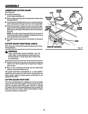
... WARNING: Cutter guard helps provide protection over the cutter head between the guard and the fence. If the stop post does not stop post limits the amount of cutter guard travel. n Locate the following: Cutter Guard Assembly (1) n Remove the pan head screw from contact with a punch or nail set. n ... of wood over the cutter head. The guard must always be in the infeed table. TOP VIEW GUARD SPRING KNOB Fig. 24 20 ASSEMBLY ASSEMBLING CUTTER GUARD See Figure 24. Slide the post through the hole in place and functioning properly to the rear of the bed for proper ...
... WARNING: Cutter guard helps provide protection over the cutter head between the guard and the fence. If the stop post does not stop post limits the amount of cutter guard travel. n Locate the following: Cutter Guard Assembly (1) n Remove the pan head screw from contact with a punch or nail set. n ... of wood over the cutter head. The guard must always be in the infeed table. TOP VIEW GUARD SPRING KNOB Fig. 24 20 ASSEMBLY ASSEMBLING CUTTER GUARD See Figure 24. Slide the post through the hole in place and functioning properly to the rear of the bed for proper ...
Owners Manual
Page 31
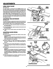
...head guard in service. Overtightening may cause premature spring or guard breakage. To assemble the gauge slide the one side to set the fence at the end of the fence on one side over the other . Simply set the gauge at the ...Check as follows. There is also a 0°-45° protractor on the outfeed table as shown and set the fence to the outfeed table. In the event that attach the extension to an angle not provided. n Loosen the hex ... tension knob clockwise. n Remove tension on cutter head guard to be flush with the RIDGID jointer to set the angle you need.
...head guard in service. Overtightening may cause premature spring or guard breakage. To assemble the gauge slide the one side to set the fence at the end of the fence on one side over the other . Simply set the gauge at the ...Check as follows. There is also a 0°-45° protractor on the outfeed table as shown and set the fence to the outfeed table. In the event that attach the extension to an angle not provided. n Loosen the hex ... tension knob clockwise. n Remove tension on cutter head guard to be flush with the RIDGID jointer to set the angle you need.

