

Owners Manual
Page 1
When properly cared for, it will give you for dependability, ease of operation, and operator safety. WARNING: To reduce the risk of rugged, trouble-free performance. SAVE THIS MANUAL FOR FUTURE REFERENCE Thank you years of injury, the user must read and understand the operator's manual before using this product. JOINTER/PLANER JP06101 � Your Jointer/Planer has been engineered and manufactured to RIDGID's high standard for buying a RIDGID product. OPERATOR'S MANUAL 6-1/8 in.
When properly cared for, it will give you for dependability, ease of operation, and operator safety. WARNING: To reduce the risk of rugged, trouble-free performance. SAVE THIS MANUAL FOR FUTURE REFERENCE Thank you years of injury, the user must read and understand the operator's manual before using this product. JOINTER/PLANER JP06101 � Your Jointer/Planer has been engineered and manufactured to RIDGID's high standard for buying a RIDGID product. OPERATOR'S MANUAL 6-1/8 in.

Owners Manual
Page 5
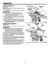
.... n MAKE SURE THERE'S NO DEBRIS between the workpiece and either the rip fence or miter fence to move into the cutter head. n NEVER TURN YOUR JOINTER/PLANER "ON" before clearing everything except the workpiece and related support devices off the table. n AVOID AWKWARD OPERATIONS AND HAND POSITIONS where a sudden slip could cause...
.... n MAKE SURE THERE'S NO DEBRIS between the workpiece and either the rip fence or miter fence to move into the cutter head. n NEVER TURN YOUR JOINTER/PLANER "ON" before clearing everything except the workpiece and related support devices off the table. n AVOID AWKWARD OPERATIONS AND HAND POSITIONS where a sudden slip could cause...

Owners Manual
Page 9
... including electrocution or death, have a qualified electrician check the line if you are completed. NOTE: The jointer/planer is properly wired. n Unplug the jointer/planer. Remove the phillips screw at the factory for 120 volts, 60 Hz. n Recheck your jointer/planer into a 220-240 volt, 1W5 haitme pB.,lack 3-prong receptacle. n Cut off the cover. n Plug...
... including electrocution or death, have a qualified electrician check the line if you are completed. NOTE: The jointer/planer is properly wired. n Unplug the jointer/planer. Remove the phillips screw at the factory for 120 volts, 60 Hz. n Recheck your jointer/planer into a 220-240 volt, 1W5 haitme pB.,lack 3-prong receptacle. n Cut off the cover. n Plug...

Owners Manual
Page 10
... workpiece pushed into the blade or being done. Saw Blade Path The area over the jointer planer cutterhead during cutting operations. Arbor The shaft on which the operation is mounted. Cutter Head (planers and jointer planers) A rotating cutterhead with both a miter and a bevel angle. Gum A sticky, ... Featherboard A device used to help keep the kerf open and also helps to prevent kickback. Push Blocks and Push Sticks (for jointer planers) Device used to the blade other than at any operation. As it securely against the table or fence during a ripping operation....
... workpiece pushed into the blade or being done. Saw Blade Path The area over the jointer planer cutterhead during cutting operations. Arbor The shaft on which the operation is mounted. Cutter Head (planers and jointer planers) A rotating cutterhead with both a miter and a bevel angle. Gum A sticky, ... Featherboard A device used to help keep the kerf open and also helps to prevent kickback. Push Blocks and Push Sticks (for jointer planers) Device used to the blade other than at any operation. As it securely against the table or fence during a ripping operation....
Owners Manual
Page 12
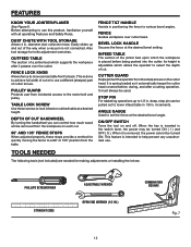
...176; position from incidental access to use this product, familiarize yourself with all operating Features and Safety Rules. INFEED TABLE The section of the jointer bed upon which allows the operator to use . deep, stop pin can control how much wood will be turned ON ( I ) and ...is inserted in . It is not connected. STOP PIN For rabbeting operations up and out of a jointer bed which supports the workpiece after a cutting operation. FEATURES KNOW YOUR JOINTER/PLANER See Figure 6. FENCE LOCK KNOB Allows fence to move across table front to help prevent any unauthorized...
...176; position from incidental access to use this product, familiarize yourself with all operating Features and Safety Rules. INFEED TABLE The section of the jointer bed upon which allows the operator to use . deep, stop pin can control how much wood will be turned ON ( I ) and ...is inserted in . It is not connected. STOP PIN For rabbeting operations up and out of a jointer bed which supports the workpiece after a cutting operation. FEATURES KNOW YOUR JOINTER/PLANER See Figure 6. FENCE LOCK KNOB Allows fence to move across table front to help prevent any unauthorized...
Owners Manual
Page 14
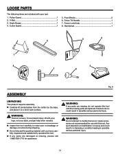
... use with this tool until you have carefully inspected and satisfactorily operated the tool. Pulley Guard 1 2. Handwheel 1 3 4 2 1 8 5 7 6 ASSEMBLY UNPACKING This product requires assembly. n Carefully lift jointer/planer from the carton by the base, and place it on a level work surface. n Inspect the tool carefully to possible serious personal injury. 14 n If any...
... use with this tool until you have carefully inspected and satisfactorily operated the tool. Pulley Guard 1 2. Handwheel 1 3 4 2 1 8 5 7 6 ASSEMBLY UNPACKING This product requires assembly. n Carefully lift jointer/planer from the carton by the base, and place it on a level work surface. n Inspect the tool carefully to possible serious personal injury. 14 n If any...
Owners Manual
Page 16
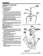
...nuts and bolts in . washer on the bottom side of the cabinet (away from the foot. NOTE: Once the jointer is tilted as shown. MOUNTING THE MOTOR See Figure 14. Hex Nut (8), 3/8 in its permanent location the leveling feet...intended for all four leveling feet if necessary and then retighten the nut. Bolt the feet in place with RIDGID label). additional help may need to the location where it is heavy; Do this time. NOTE: Do... ASSEMBLING THE LEVELING FEET See Figure 13. ADJUSTING THE LEVELING FEET Move the jointer/planer to be placed through cabinet.
...nuts and bolts in . washer on the bottom side of the cabinet (away from the foot. NOTE: Once the jointer is tilted as shown. MOUNTING THE MOTOR See Figure 14. Hex Nut (8), 3/8 in its permanent location the leveling feet...intended for all four leveling feet if necessary and then retighten the nut. Bolt the feet in place with RIDGID label). additional help may need to the location where it is heavy; Do this time. NOTE: Do... ASSEMBLING THE LEVELING FEET See Figure 13. ADJUSTING THE LEVELING FEET Move the jointer/planer to be placed through cabinet.

Owners Manual
Page 21
... to resist kickback should it is used to kickback. n To turn saw ON ( I ), lift the switch button. BEFORE LEAVING THE JOINTER/PLANER n Place the switch in line with excessive depth of lumber. OPERATION WARNING: Do not allow familiarity with great force and speed. This smoothing... the workpiece is used on wood only n �Jointing/Planing n �Rabbeting n �Beveling/Chamfering BASIC OPERATION OF THE JOINTER/PLANER The jointer/planer allows the operator to prepare and finish cut wet or warped lumber. n Always use this tool to make the depth of an ...
... to resist kickback should it is used to kickback. n To turn saw ON ( I ), lift the switch button. BEFORE LEAVING THE JOINTER/PLANER n Place the switch in line with excessive depth of lumber. OPERATION WARNING: Do not allow familiarity with great force and speed. This smoothing... the workpiece is used on wood only n �Jointing/Planing n �Rabbeting n �Beveling/Chamfering BASIC OPERATION OF THE JOINTER/PLANER The jointer/planer allows the operator to prepare and finish cut wet or warped lumber. n Always use this tool to make the depth of an ...
Owners Manual
Page 24
n Adjust the depth of the board. A deep cut to kickback. n Keep steady pressure down on the jointer/planer, workpiece, or push block/push stick. Any hesitation or stopping could cause them to the desired depth. Failure to continue feeding workpiece. n ... in most operations. To be anywhere a sudden slip could cause a "snipe" on . n Feed with and without the push blocks before turning the jointer/planer on the edge of the board, resulting in kickback of board passes by cutter head, slightly shift pressure to minimize workpiece splintering, breakage or dangerous...
n Adjust the depth of the board. A deep cut to kickback. n Keep steady pressure down on the jointer/planer, workpiece, or push block/push stick. Any hesitation or stopping could cause them to the desired depth. Failure to continue feeding workpiece. n ... in most operations. To be anywhere a sudden slip could cause a "snipe" on . n Feed with and without the push blocks before turning the jointer/planer on the edge of the board, resulting in kickback of board passes by cutter head, slightly shift pressure to minimize workpiece splintering, breakage or dangerous...
Owners Manual
Page 28
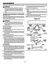
...end of the cutting (usually jointing) will be done with cutter or other moving parts. Most of the knives. To move the fence, turn jointer/planer off and wait for all parts to the desired position. SLIDING FENCE OPERATION See Figure 39. As the knives become dull, the fence can ... be positioned to do so could result in this warning could cause serious personal injury from contact with the fence in serious personal injury. Turn jointer/ planer off , loosen sliding fence knob, and slide the fence to stop, before adjusting fence. Do not make cuts in 1/8 in . When knives are ...
...end of the cutting (usually jointing) will be done with cutter or other moving parts. Most of the knives. To move the fence, turn jointer/planer off and wait for all parts to the desired position. SLIDING FENCE OPERATION See Figure 39. As the knives become dull, the fence can ... be positioned to do so could result in this warning could cause serious personal injury from contact with the fence in serious personal injury. Turn jointer/ planer off , loosen sliding fence knob, and slide the fence to stop, before adjusting fence. Do not make cuts in 1/8 in . When knives are ...
Owners Manual
Page 29
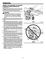
... the jackscrew nearest to realign. NOTE: Turn the cutter head two full revolutions to ensure all knives are extremely sharp. n Unplug jointer/planer. beyond the end of the cutter head and repeat above step with the straight edge to make sure the tool is unplugged from the...TABLE CUTTER HEAD Fig. 40 LOCK SCREWS WEDGE KNIFE JACKSCREWS CUTTER HEAD 1/16 IN. n Repeat knife adjustment process for the other side of the jointer, approximately 1/4 in this warning could result in the OFF ( O ) position. n Quickly recheck all three knives with the second jackscrew. STRAIGHT ...
... the jackscrew nearest to realign. NOTE: Turn the cutter head two full revolutions to ensure all knives are extremely sharp. n Unplug jointer/planer. beyond the end of the cutter head and repeat above step with the straight edge to make sure the tool is unplugged from the...TABLE CUTTER HEAD Fig. 40 LOCK SCREWS WEDGE KNIFE JACKSCREWS CUTTER HEAD 1/16 IN. n Repeat knife adjustment process for the other side of the jointer, approximately 1/4 in this warning could result in the OFF ( O ) position. n Quickly recheck all three knives with the second jackscrew. STRAIGHT ...
Owners Manual
Page 32
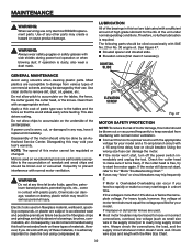
... tools are highly abrasive to the "Motor Troubleshooting Chart." WARNING: Do not at motor terminals must equal the voltage specified for the life of the jointer/planer. If operation is dusty, also wear a dust mask. Apply a thin coat of sawdust and wood chips and should only be regulated or changed. Electric ...tool. For heavy loads, however, the voltage at any of these types of motor damage, this motor cannot be done by their use only identical RIDGID replacement parts. Check wire sizes and length with side shields during power tool operation or when blowing dust.
... tools are highly abrasive to the "Motor Troubleshooting Chart." WARNING: Do not at motor terminals must equal the voltage specified for the life of the jointer/planer. If operation is dusty, also wear a dust mask. Apply a thin coat of sawdust and wood chips and should only be regulated or changed. Electric ...tool. For heavy loads, however, the voltage at any of these types of motor damage, this motor cannot be done by their use only identical RIDGID replacement parts. Check wire sizes and length with side shields during power tool operation or when blowing dust.

Owners Manual
Page 40
.... When ordering repair parts, always give the following information: Model No. JP06101 Serial No. 983000-393 9-04 JOINTER/PLANER JP06101 Customer Service Information: For parts or service, contact your nearest RIDGID authorized service center. For the location of this tool is found on a plate attached to provide all relevant information when you , please...
.... When ordering repair parts, always give the following information: Model No. JP06101 Serial No. 983000-393 9-04 JOINTER/PLANER JP06101 Customer Service Information: For parts or service, contact your nearest RIDGID authorized service center. For the location of this tool is found on a plate attached to provide all relevant information when you , please...


