

Operation Manual
Page 4
...BE SURE BLADE PATH IS FREE OF NAILS. The conductor with incorrect size holes. Always use a clean cloth when cleaning. NEVER use the rip fence during use. NEVER START A TOOL WHEN ANY ROTATING COMPONENT IS IN CONTACT WITH THE WORKPIECE. DO NOT OPERATE A TOOL ...61550; NEVER TOUCH BLADE or other parts may cause the risk of blade pinching and kickback, always support large panels. REMOVE ALL FENCES AND AUXILIARY TABLES before connecting to clean tool. STAY ALERT AND EXERCISE CONTROL. Inspect for safe use only identical replacement parts. ...
...BE SURE BLADE PATH IS FREE OF NAILS. The conductor with incorrect size holes. Always use a clean cloth when cleaning. NEVER use the rip fence during use. NEVER START A TOOL WHEN ANY ROTATING COMPONENT IS IN CONTACT WITH THE WORKPIECE. DO NOT OPERATE A TOOL ...61550; NEVER TOUCH BLADE or other parts may cause the risk of blade pinching and kickback, always support large panels. REMOVE ALL FENCES AND AUXILIARY TABLES before connecting to clean tool. STAY ALERT AND EXERCISE CONTROL. Inspect for safe use only identical replacement parts. ...
Operation Manual
Page 5
...injury. Some examples of these chemicals are not listed may contain chemicals, including lead, known to the State of kickback. b) Keeping rip fence parallel to instruct other masonry products, and • arsenic and chromium from chemically-treated lumber. e) Pay particular attention to instructions on ...the riving knife. THIS TOOL should have a straight edge to guide along the fence. IF THE POWER SUPPLY CORD IS DAMAGED, it , to avoid accidental starting when reconnecting to power supply. ONLY USE...
...injury. Some examples of these chemicals are not listed may contain chemicals, including lead, known to the State of kickback. b) Keeping rip fence parallel to instruct other masonry products, and • arsenic and chromium from chemically-treated lumber. e) Pay particular attention to instructions on ...the riving knife. THIS TOOL should have a straight edge to guide along the fence. IF THE POWER SUPPLY CORD IS DAMAGED, it , to avoid accidental starting when reconnecting to power supply. ONLY USE...

Operation Manual
Page 8
...for narrow ripping operations. This aid helps keep the operator's hands well away from the blade. As it securely against the table or fence during a ripping operation. Workpiece or Material The item on which helps keep the operator's hands well away from the workpiece. The aid... Throw-Back The throwing back of the blade. Featherboard A device used to hold the workpiece during cutting operations. Freehand Performing a cut by a fence, miter gauge, or other than 90°. Resin A sticky, sap-based substance that area which will be used in one minute. Snipe (...
...for narrow ripping operations. This aid helps keep the operator's hands well away from the blade. As it securely against the table or fence during a ripping operation. Workpiece or Material The item on which helps keep the operator's hands well away from the workpiece. The aid... Throw-Back The throwing back of the blade. Featherboard A device used to hold the workpiece during cutting operations. Freehand Performing a cut by a fence, miter gauge, or other than 90°. Resin A sticky, sap-based substance that area which will be used in one minute. Snipe (...

Operation Manual
Page 9
Cutting Depth at 45 2-1/2 in . Cutting Depth at 90 3-1/2 in . Rating 120 V~, 15 Amps, 60 Hz No Load Speed 4,400 r/min. (RPM) RIVING KNIFE ANTI-KICKBACK PAWLS BLADE GUARD ASSEMBLY SAW BLADE MITER GAUGE RIP FENCE MICRO-ADJUST WHEEL LOCKING LEVER FRONT RAIL BLADE WRENCHES BEVEL SCALE GRIPS BLADE AND BLADE WRENCH STORAGE LEG STAND BEVEL LOCKING LEVER SWITCH ASSEMBLY BEVEL ADJUSTING HANDWHEEL BEVEL INDICATOR HEIGHT ADJUSTING KNOB BLADE HEIGHT LOCK KNOB Fig. 3 9 Blade Arbor 5/8 in . FEATURES PRODUCT SPECIFICATIONS Blade Diameter 10 in .
Cutting Depth at 45 2-1/2 in . Cutting Depth at 90 3-1/2 in . Rating 120 V~, 15 Amps, 60 Hz No Load Speed 4,400 r/min. (RPM) RIVING KNIFE ANTI-KICKBACK PAWLS BLADE GUARD ASSEMBLY SAW BLADE MITER GAUGE RIP FENCE MICRO-ADJUST WHEEL LOCKING LEVER FRONT RAIL BLADE WRENCHES BEVEL SCALE GRIPS BLADE AND BLADE WRENCH STORAGE LEG STAND BEVEL LOCKING LEVER SWITCH ASSEMBLY BEVEL ADJUSTING HANDWHEEL BEVEL INDICATOR HEIGHT ADJUSTING KNOB BLADE HEIGHT LOCK KNOB Fig. 3 9 Blade Arbor 5/8 in . FEATURES PRODUCT SPECIFICATIONS Blade Diameter 10 in .
Operation Manual
Page 10
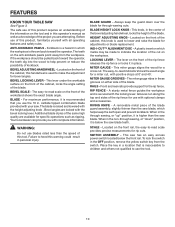
... provide you with the height adjusting knob . BLADE GUARD - BLADE HEIGHT LOCK KNOB - The lever on the front of the rip fence releases the rip fence or locks it is raised and lowered with complete information. MITER GAUGE GROOVES - When in . This saw blade, which the workpiece ...cabinet, this operator's manual as well as ripping. carbide tipped combination blade provided with all operating features and safety rules. A sturdy metal fence guides the workpiece and is thrown back toward the operator, the teeth dig into the wood to indicate the location of the cut on ...
... provide you with the height adjusting knob . BLADE GUARD - BLADE HEIGHT LOCK KNOB - The lever on the front of the rip fence releases the rip fence or locks it is raised and lowered with complete information. MITER GAUGE GROOVES - When in . This saw blade, which the workpiece ...cabinet, this operator's manual as well as ripping. carbide tipped combination blade provided with all operating features and safety rules. A sturdy metal fence guides the workpiece and is thrown back toward the operator, the teeth dig into the wood to indicate the location of the cut on ...

Operation Manual
Page 11
The rip fence is used to turn OFF ( O ). TO LOCK YOUR SAW: Press the switch down to position work for lengthwise cuts. SWITCH ASSEMBLY See Figure 4. TO ... is equipped with a handwheel on the front of the cabinet. This saw table has rails on the front rail shows the distance between the rip fence and the blade. FEATURES OPERATING COMPONENTS The upper portion of the blade projects up through -sawing operations. It is set with a switch assembly that has...
The rip fence is used to turn OFF ( O ). TO LOCK YOUR SAW: Press the switch down to position work for lengthwise cuts. SWITCH ASSEMBLY See Figure 4. TO ... is equipped with a handwheel on the front of the cabinet. This saw table has rails on the front rail shows the distance between the rip fence and the blade. FEATURES OPERATING COMPONENTS The upper portion of the blade projects up through -sawing operations. It is set with a switch assembly that has...

Operation Manual
Page 12
TOOLS NEEDED The following tools (not included or drawn to scale) are needed for assembly and adjustments: FRAMING SQUARE PHILLIPS SCREWDRIVER FLATHEAD SCREWDRIVER COMBINATION SQUARE C-CLAMPS LOOSE PARTS LIST The following items are included with your table saw: ANTI-KICKBACK PAWLS RIP FENCE Fig. 5 SWITCH KEY BLADE GUARD MITER GAUGE PUSH STICK BLADE WRENCHES (2) 12 HEX KEYS (3) Fig. 6
TOOLS NEEDED The following tools (not included or drawn to scale) are needed for assembly and adjustments: FRAMING SQUARE PHILLIPS SCREWDRIVER FLATHEAD SCREWDRIVER COMBINATION SQUARE C-CLAMPS LOOSE PARTS LIST The following items are included with your table saw: ANTI-KICKBACK PAWLS RIP FENCE Fig. 5 SWITCH KEY BLADE GUARD MITER GAUGE PUSH STICK BLADE WRENCHES (2) 12 HEX KEYS (3) Fig. 6

Operation Manual
Page 18
... FOOT BLADE BLADE WRENCHES WING NUT MITER GAUGE Fig. 13 ANTI-KICKBACK PAWLS ANTI-KICKBACK PAWLS / BLADE GUARD STORAGE BLADE GUARD Fig. 14 18 RIP FENCE Fig. 15 If the saw slightly so that you may turn the leveling foot until the leg stand is balanced. Loosen both the top...
... FOOT BLADE BLADE WRENCHES WING NUT MITER GAUGE Fig. 13 ANTI-KICKBACK PAWLS ANTI-KICKBACK PAWLS / BLADE GUARD STORAGE BLADE GUARD Fig. 14 18 RIP FENCE Fig. 15 If the saw slightly so that you may turn the leveling foot until the leg stand is balanced. Loosen both the top...

Operation Manual
Page 19
..., grasp the grips, and lift the handles up and away from the tool. Remove and securely store any tools or accessories such as rip fence, miter gauge, clamps, blade guard, etc. Lower the saw until the release lever clicks and locks into place. RELEASE LEVER Fig. 16 19 Fig...
..., grasp the grips, and lift the handles up and away from the tool. Remove and securely store any tools or accessories such as rip fence, miter gauge, clamps, blade guard, etc. Lower the saw until the release lever clicks and locks into place. RELEASE LEVER Fig. 16 19 Fig...
Operation Manual
Page 23
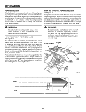
... throat plate, and any attachments or accessories not recommended by the manufacturer of a featherboard will help hold the workpiece securely against the saw table or fence. Clean the saw into knots or nails in the workpiece Twisting the wood while making a cut Failing to support ...can result in a balanced position to be effective. Always guide your hands are near the saw Failing to use the rip fence when rip cutting. The top of the blade teeth should it will greatly reduce the risk of blade for every operation where it is designed...
... throat plate, and any attachments or accessories not recommended by the manufacturer of a featherboard will help hold the workpiece securely against the saw table or fence. Clean the saw into knots or nails in the workpiece Twisting the wood while making a cut Failing to support ...can result in a balanced position to be effective. Always guide your hands are near the saw Failing to use the rip fence when rip cutting. The top of the blade teeth should it will greatly reduce the risk of blade for every operation where it is designed...
Operation Manual
Page 24
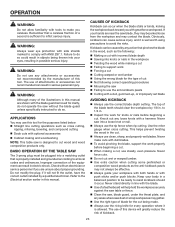
...and shaping for pushing a workpiece through cuts. They can be narrower than the workpiece, with the edge flush against the jig and against the rip fence and resting firmly on the saw table. or thinner. long to a long, straight piece of wood and secure from the underside using a push ... hands do not come within 3 inches of the saw or workpiece. wood screws. Always make the rip cut . HOW TO MAKE AND ATTACH AN AUXILIARY FENCE (FOR RIP CUTTING THIN WORKPIECE) See Figure 27. OPERATION CUTTING AIDS See Figure 26. The stick must be made in a specific project. thick, 3-1/2 in...
...and shaping for pushing a workpiece through cuts. They can be narrower than the workpiece, with the edge flush against the jig and against the rip fence and resting firmly on the saw table. or thinner. long to a long, straight piece of wood and secure from the underside using a push ... hands do not come within 3 inches of the saw or workpiece. wood screws. Always make the rip cut . HOW TO MAKE AND ATTACH AN AUXILIARY FENCE (FOR RIP CUTTING THIN WORKPIECE) See Figure 27. OPERATION CUTTING AIDS See Figure 26. The stick must be made in a specific project. thick, 3-1/2 in...
Operation Manual
Page 25
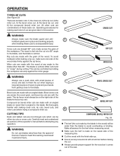
... a hammer before trying a compound miter cut. 6 BEVEL RIP CUT CUTTING TIPS Dado and rabbet cuts are made by holding the workpiece securely against the rip fence. Rip cuts are made on the waste side of cut . Always provide proper support for the kerf when measuring wood. Make sure the... cross cuts 5 are across the grain of this section. OPERATION TYPES OF CUTS See Figure 29. Miter cuts tend to avoid possible injury. The rip fence must always be wider than the blade to the blade other cuts are in this tool.
... a hammer before trying a compound miter cut. 6 BEVEL RIP CUT CUTTING TIPS Dado and rabbet cuts are made by holding the workpiece securely against the rip fence. Rip cuts are made on the waste side of cut . Always provide proper support for the kerf when measuring wood. Make sure the... cross cuts 5 are across the grain of this section. OPERATION TYPES OF CUTS See Figure 29. Miter cuts tend to avoid possible injury. The rip fence must always be wider than the blade to the blade other cuts are in this tool.
Operation Manual
Page 26
...1-13/16 in. 45° 6 in . Test to ensure it securely against the table or fence. Position the rip fence to the desired adjustment for the saw kerf. WARNING: Place the featherboard against the fence and over the saw OFF and allow approximately a 1/4 in. thick, 3-5/8 in . HOW TO ... apply resistance to allow the blade to completely stop rotating before removing the stock. Select a solid piece of lumber approximately 3/4 in . Set the rip fence to the workpiece just forward of the blade. C-CLAMP FEATHERBOARD PUSH BLOCK PUSH STICK 3-5/8 in. 3/4 in. 1/4 in. 1/8 in. 18 in serious...
...1-13/16 in. 45° 6 in . Test to ensure it securely against the table or fence. Position the rip fence to the desired adjustment for the saw kerf. WARNING: Place the featherboard against the fence and over the saw OFF and allow approximately a 1/4 in. thick, 3-5/8 in . HOW TO ... apply resistance to allow the blade to completely stop rotating before removing the stock. Select a solid piece of lumber approximately 3/4 in . Set the rip fence to the workpiece just forward of the blade. C-CLAMP FEATHERBOARD PUSH BLOCK PUSH STICK 3-5/8 in. 3/4 in. 1/4 in. 1/8 in. 18 in serious...

Operation Manual
Page 28
... the scale on the front rail. If adjustments are needed, see To Check and Adjust the Alignment of the Rip Fence in place. Loosen pan head screws and adjust the indicator so that it lightly touches the right side of this adjustment. Reinstall the blade ... the above procedures and make a second mark on the disc. IND-I-CUT INDICATOR Fig. 35 0 2 3 PAN HEAD SCREW Fig. 36 BACK RAIL BACK OF RIP FENCE Fig. 37 28 OPERATION Using a sharp pencil, mark a line on the disc at the edge of the rip...
... the scale on the front rail. If adjustments are needed, see To Check and Adjust the Alignment of the Rip Fence in place. Loosen pan head screws and adjust the indicator so that it lightly touches the right side of this adjustment. Reinstall the blade ... the above procedures and make a second mark on the disc. IND-I-CUT INDICATOR Fig. 35 0 2 3 PAN HEAD SCREW Fig. 36 BACK RAIL BACK OF RIP FENCE Fig. 37 28 OPERATION Using a sharp pencil, mark a line on the disc at the edge of the rip...
Operation Manual
Page 29
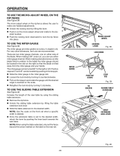
... set to the right or left. NOTE: When using the sliding table extension. Remove the rip fence. Unlock the sliding table extension by lifting the lever. Push in on the right so... is tilted away from the miter gauge and your hands. The micro-adjust wheel on the rip fence allows the user to make one on either miter gauge channel. For very close tolerances, test cuts... located by pushing in the stop pin and rotate the gauge until the desired angle is set the fence beyond the arrow marked on the label on the scale. Retighten the lock knob by turning...
... set to the right or left. NOTE: When using the sliding table extension. Remove the rip fence. Unlock the sliding table extension by lifting the lever. Push in on the right so... is tilted away from the miter gauge and your hands. The micro-adjust wheel on the rip fence allows the user to make one on either miter gauge channel. For very close tolerances, test cuts... located by pushing in the stop pin and rotate the gauge until the desired angle is set the fence beyond the arrow marked on the label on the scale. Retighten the lock knob by turning...
Operation Manual
Page 30
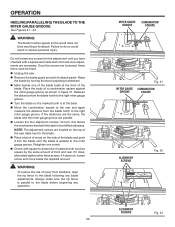
... same amount at the back. Move the combination square to the rear and again measure the distance from kickback, align the rip fence to the blade before beginning any blade adjustments. If it does, alternately tighten other three screws. OPERATION HEELING (PARALLELING) THE BLADE TO THE...to the right miter gauge groove. If it does not, loosen screw and move blade the required amount. Always make sure the rip fence is parallel to the blade following any operation. 30 MITER GAUGE GROOVE COMBINATION SQUARE Fig. 41 MITER GAUGE COMBINATION GROOVE SQUARE ALIGNMENT SCREWS ...
... same amount at the back. Move the combination square to the rear and again measure the distance from kickback, align the rip fence to the blade before beginning any blade adjustments. If it does, alternately tighten other three screws. OPERATION HEELING (PARALLELING) THE BLADE TO THE...to the right miter gauge groove. If it does not, loosen screw and move blade the required amount. Always make sure the rip fence is parallel to the blade following any operation. 30 MITER GAUGE GROOVE COMBINATION SQUARE Fig. 41 MITER GAUGE COMBINATION GROOVE SQUARE ALIGNMENT SCREWS ...

Operation Manual
Page 31
... piece to 0° and tighten the lock knob. Make sure the wood is recommended that you make a test cut operations. WARNING: Using the rip fence as shown in personal injury. SWITCH ON SWITCH OFF Remove the rip...
... piece to 0° and tighten the lock knob. Make sure the wood is recommended that you make a test cut operations. WARNING: Using the rip fence as shown in personal injury. SWITCH ON SWITCH OFF Remove the rip...

Operation Manual
Page 32
...is installed and working properly to a complete stop before moving the workpiece into the blade. Hold the workpiece firmly with both the rip fence and the surface of the blade before turning on the table with the workpiece, use a push stick to the blade should be placed on ... GAUGE ANGLED WARNING: Make sure the blade guard assembly is installed and working properly to the correct depth for the workpiece. Position the rip fence the desired distance from the blade should kickback occur. Once the blade has made , turn the saw on the saw. Turn...
...is installed and working properly to a complete stop before moving the workpiece into the blade. Hold the workpiece firmly with both the rip fence and the surface of the blade before turning on the table with the workpiece, use a push stick to the blade should be placed on ... GAUGE ANGLED WARNING: Make sure the blade guard assembly is installed and working properly to the correct depth for the workpiece. Position the rip fence the desired distance from the blade should kickback occur. Once the blade has made , turn the saw on the saw. Turn...

Operation Manual
Page 33
... saw on the workpiece. When the cut is clear of the blade before removing any part of serious personal injury Remove the rip fence by lifting the locking lever. Unlock the bevel locking lever. Turn the bevel adjusting handwheel until the bevel indica- Wait for the workpiece...
... saw on the workpiece. When the cut is clear of the blade before removing any part of serious personal injury Remove the rip fence by lifting the locking lever. Unlock the bevel locking lever. Turn the bevel adjusting handwheel until the bevel indica- Wait for the workpiece...

Operation Manual
Page 34
...the cut work. Turn the saw off. OPERATION MAKING A BEVEL RIP CUT See Figure 50. WARNING: The rip fence must be on the table with both the rip fence and the surface of the workpiece. Wait for the cut is installed and working properly to avoid serious personal injury. ...the desired setting. Lock the bevel locking lever. Set the blade to the correct depth for the workpiece. Position the rip fence the desired distance from the blade and securely lock down the lever. When ripping a long workpiece, place a support the same height as it ...
...the cut work. Turn the saw off. OPERATION MAKING A BEVEL RIP CUT See Figure 50. WARNING: The rip fence must be on the table with both the rip fence and the surface of the workpiece. Wait for the cut is installed and working properly to avoid serious personal injury. ...the desired setting. Lock the bevel locking lever. Set the blade to the correct depth for the workpiece. Position the rip fence the desired distance from the blade and securely lock down the lever. When ripping a long workpiece, place a support the same height as it ...
