Instructions for Use
Page 8
Delivery includes Delivery includes The packaging contains the following items: 1 EM 100 G3 stationary receiver 1 NT 2-3 or NT 2-1 mains unit with one country adapter 2 rod antennas 2 stacking elements 1 instruction manual 1 frequency information sheet 4 device feet 7
Delivery includes Delivery includes The packaging contains the following items: 1 EM 100 G3 stationary receiver 1 NT 2-3 or NT 2-1 mains unit with one country adapter 2 rod antennas 2 stacking elements 1 instruction manual 1 frequency information sheet 4 device feet 7

Instructions for Use
Page 9
... ¼" (6.3 mm) jack socket, unbalanced ¸ Service interface (DATA) ¹ Service interface (DATA) Ƹ Antenna input II (ANT II) with remote power supply input, BNC socket ƹ Type plate ƺ Antenna input I (ANT I) with remote power supply input, BNC socket 8 ESC function (cancel) B Operating elements - front... panel ¶ Cable grip for power supply DC cable º DC socket (DC IN) for connection of the EM 100 G3 receiver ³· » ¿ ´² A PEAK 20.12 ew100 G3 533.875 40 0 P 25 10 -10 -20 -30 RF AF MHz SET B XXXXXXX 0682 ƹ &#...
... ¼" (6.3 mm) jack socket, unbalanced ¸ Service interface (DATA) ¹ Service interface (DATA) Ƹ Antenna input II (ANT II) with remote power supply input, BNC socket ƹ Type plate ƺ Antenna input I (ANT I) with remote power supply input, BNC socket 8 ESC function (cancel) B Operating elements - front... panel ¶ Cable grip for power supply DC cable º DC socket (DC IN) for connection of the EM 100 G3 receiver ³· » ¿ ´² A PEAK 20.12 ew100 G3 533.875 40 0 P 25 10 -10 -20 -30 RF AF MHz SET B XXXXXXX 0682 ƹ &#...
Instructions for Use
Page 10
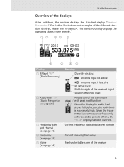
... level is shown inverted. This standard display displays the operating states of the receiver. 533.875 40 25 10 RF PEAK 0 20.12 -10 ew100 G3 MHz -20 -30 AF P MUTE ቧ ቨ ቩቪ Display ቢ RF level "RF" (Radio Frequency) ባ Audio level "AF" (Audio ...4708; Frequency bank and channel (see page 35) ብ Frequency (see page 35) ቦ Name (see page 36) Meaning Diversity display: Antenna input I is active 40 Antenna input II is active 25 10 RF signal level: RF Field strength of the received signal Squelch threshold level PEAK 0 -10 -20 -30...
... level is shown inverted. This standard display displays the operating states of the receiver. 533.875 40 25 10 RF PEAK 0 20.12 -10 ew100 G3 MHz -20 -30 AF P MUTE ቧ ቨ ቩቪ Display ቢ RF level "RF" (Radio Frequency) ባ Audio level "AF" (Audio ...4708; Frequency bank and channel (see page 35) ብ Frequency (see page 35) ቦ Name (see page 36) Meaning Diversity display: Antenna input I is active 40 Antenna input II is active 25 10 RF signal level: RF Field strength of the received signal Squelch threshold level PEAK 0 -10 -20 -30...
Instructions for Use
Page 12
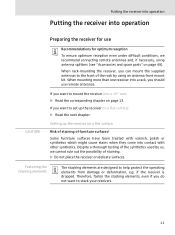
... if the receiver is dropped. Fastening the stacking elements The stacking elements are designed to the front of the synthetics used by using antenna splitters (see "Accessories and spare parts" on page 49). When rack-mounting the receiver, you want to mount the receiver into ... 11 CAUTION! Despite a thorough testing of the rack by us, we recommend connecting remote antennas and, if necessary, using an antenna front mount kit. If you can mount the supplied antennas to help protect the operating elements from damage or deformation, e.g. Some furniture surfaces have been...
... if the receiver is dropped. Fastening the stacking elements The stacking elements are designed to the front of the synthetics used by using antenna splitters (see "Accessories and spare parts" on page 49). When rack-mounting the receiver, you want to mount the receiver into ... 11 CAUTION! Despite a thorough testing of the rack by us, we recommend connecting remote antennas and, if necessary, using an antenna front mount kit. If you can mount the supplied antennas to help protect the operating elements from damage or deformation, e.g. Some furniture surfaces have been...
Instructions for Use
Page 14
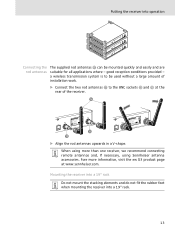
...G3 product page at the rear of installation work. ̈ Connect the two rod antennas Ƽ to be mounted quickly and easily and are suitable for all applications where - Putting the receiver into a 19" rack. 13 XXX MHz DESIGNED IN GERMANY, ASSEMBLED IN USA Ƹ ƺ EM 100... antennas The supplied rod antennas Ƽ can be used without a large amount of the receiver. ƻ EM 100 0682 FTISIDCERR:EREU2N.Q0ENT9..ODR9N.AIA:OV-N.E: RGXXSXXEXIXX-TXXXYXXXXRXXXXEXXX:CXXEXXIXVXER- a wireless transmission system is to the BNC sockets Ƹ and ƺ at www.sennheiser....
...G3 product page at the rear of installation work. ̈ Connect the two rod antennas Ƽ to be mounted quickly and easily and are suitable for all applications where - Putting the receiver into a 19" rack. 13 XXX MHz DESIGNED IN GERMANY, ASSEMBLED IN USA Ƹ ƺ EM 100... antennas The supplied rod antennas Ƽ can be used without a large amount of the receiver. ƻ EM 100 0682 FTISIDCERR:EREU2N.Q0ENT9..ODR9N.AIA:OV-N.E: RGXXSXXEXIXX-TXXXYXXXXRXXXXEXXX:CXXEXXIXVXER- a wireless transmission system is to the BNC sockets Ƹ and ƺ at www.sennheiser....
Instructions for Use
Page 16
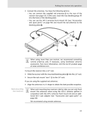
... the blanking plate . ƻ ƿ ƿ When using more information, visit the ew G3 product page at www.sennheiser.com. Fore more than one receiver, we recommend connecting remote antennas and, if necessary, using the supplied rod antennas: ̈ Align the antennas in conjunction with the mounted blanking plate ̈ Secure the rack mount "ears...
... the blanking plate . ƻ ƿ ƿ When using more information, visit the ew G3 product page at www.sennheiser.com. Fore more than one receiver, we recommend connecting remote antennas and, if necessary, using the supplied rod antennas: ̈ Align the antennas in conjunction with the mounted blanking plate ̈ Secure the rack mount "ears...
Instructions for Use
Page 17
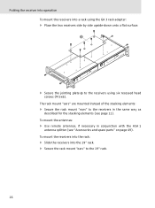
To mount the antennas: ̈ Use remote antennas, if necessary in the same way as described for the stacking elements (see "Accessories and spare parts" on page 49). To mount the receivers into ...). The rack mount "ears" are mounted instead of the stacking elements: ̈ Secure the rack mount "ears" to the receivers in conjunction with the ASA 1 antenna splitter (see page 11). Putting the receiver into operation To mount the receivers into the 19" rack. ̈ Secure the rack mount "ears" to the...
To mount the antennas: ̈ Use remote antennas, if necessary in the same way as described for the stacking elements (see "Accessories and spare parts" on page 49). To mount the receivers into ...). The rack mount "ears" are mounted instead of the stacking elements: ̈ Secure the rack mount "ears" to the receivers in conjunction with the ASA 1 antenna splitter (see page 11). Putting the receiver into operation To mount the receivers into the 19" rack. ̈ Secure the rack mount "ears" to the...
Instructions for Use
Page 33
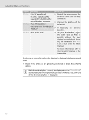
... showing full deflection (AF Max is at a level with the PEAK display). audio level What to the instruction manual of the antennas. ̈ If necessary, use antenna boosters. ̈ On your transmitter, adjust the audio level as high as possible without the level display for one or none ...of the diversity displays is displayed during the sound check: ̈ Check if the antennas are correctly connected. ̈ Improve the position of the transmitter. During normal operation of the receiver, only one of the diversity displays is ...
... showing full deflection (AF Max is at a level with the PEAK display). audio level What to the instruction manual of the antennas. ̈ If necessary, use antenna boosters. ̈ On your transmitter, adjust the audio level as high as possible without the level display for one or none ...of the diversity displays is displayed during the sound check: ̈ Check if the antennas are correctly connected. ̈ Improve the position of the transmitter. During normal operation of the receiver, only one of the diversity displays is ...

Instructions for Use
Page 47
...between two transmitters. • Use accessories recommended by Sennheiser for multi-channel applications (see page 49). 46 Recommendations and tips Recommendations and tips ... There should use two remote antennas which are connected via antenna cable. • To avoid overloading the receiver, observe... or reinforced-concrete walls). for multi-channel operation • Each of sight" between transmitting and receiving antennas. • If, with the EM 100 G3 receiver, reception conditions are unfavourable, you should be assigned freely selectable frequencies (see page 39). •...
...between two transmitters. • Use accessories recommended by Sennheiser for multi-channel applications (see page 49). 46 Recommendations and tips Recommendations and tips ... There should use two remote antennas which are connected via antenna cable. • To avoid overloading the receiver, observe... or reinforced-concrete walls). for multi-channel operation • Each of sight" between transmitting and receiving antennas. • If, with the EM 100 G3 receiver, reception conditions are unfavourable, you should be assigned freely selectable frequencies (see page 39). •...

Instructions for Use
Page 48
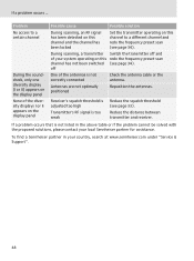
...mode is muted or doesn't Cancel the muting on the receiver (see page 20). Reduce the distance between transmitter and receiving antennas. Deactivate the pilot tone evaluation on the transmitter transmit a pilot tone (see the instruction manual of the transmitter). Problem Receiver ...is adjusted too low Adjust the transmitter sensitivity correctly (see the instruction manual of the transmitter). Reposition the antennas. Transmitter sensitivity is adjusted too high Adjust the transmitter sensitivity correctly (see the instruction manual of the transmitter). If a problem...
...mode is muted or doesn't Cancel the muting on the receiver (see page 20). Reduce the distance between transmitter and receiving antennas. Deactivate the pilot tone evaluation on the transmitter transmit a pilot tone (see the instruction manual of the transmitter). Problem Receiver ...is adjusted too low Adjust the transmitter sensitivity correctly (see the instruction manual of the transmitter). Reposition the antennas. Transmitter sensitivity is adjusted too high Adjust the transmitter sensitivity correctly (see the instruction manual of the transmitter). If a problem...
Instructions for Use
Page 49
... problem occurs that is not listed in your local Sennheiser partner for assistance. Receiver's squelch threshold is adjusted too high Transmitter's RF signal is not correctly connected Check the antenna cable or the antenna. To find a Sennheiser partner in the above table or if the problem ...cannot be solved with the proposed solutions, please contact your country, search at www.sennheiser.com under "Service & Support". 48 During ...
... problem occurs that is not listed in your local Sennheiser partner for assistance. Receiver's squelch threshold is adjusted too high Transmitter's RF signal is not correctly connected Check the antenna cable or the antenna. To find a Sennheiser partner in the above table or if the problem ...cannot be solved with the proposed solutions, please contact your country, search at www.sennheiser.com under "Service & Support". 48 During ...

Instructions for Use
Page 50
... dealer: Cat. Product name and description 503167 GA 3 rack adapter 009912 AM 2 antenna front mount kit (for GA 3 rack adapter) 503165 ASA 1 active antenna splitter, 2 x 1:4, for connecting four EM 100 G3 to two antennas/antenna boosters 503158 NT 1-1 EU Mains unit for powering the ASA 1 antenna splitter or the L 2015 charger, EU version 503873 NT 1-1 US Mains unit...
... dealer: Cat. Product name and description 503167 GA 3 rack adapter 009912 AM 2 antenna front mount kit (for GA 3 rack adapter) 503165 ASA 1 active antenna splitter, 2 x 1:4, for connecting four EM 100 G3 to two antennas/antenna boosters 503158 NT 1-1 EU Mains unit for powering the ASA 1 antenna splitter or the L 2015 charger, EU version 503873 NT 1-1 US Mains unit...
Instructions for Use
Page 51
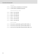
Accessories and spare parts Antennas 004645 A 1031 antenna, broadband, omni-directional 003658 A 2003 antenna, broadband, directional Antenna boosters for ASA 1 502567 AB 3-A: 516-558 MHz 502572 AB 3-G: 566-608 MHz 502568 AB 3-B: 626-668 MHz 502569 AB 3-C: 734-776 MHz 502570 AB 3-D: 780-822 MHz 502571 AB 3-E: 823-865 MHz Antenna cabels 002324 GZL 1019-A1 coaxial cable, type RG 58, BNC to BNC, 1 m 002325 GZL 1019-A5 coaxial cable, type RG 58, BNC to BNC, 5 m 002326 GZL 1019-A10 coaxial cable, type RG 58, BNC to BNC, 10 m 50
Accessories and spare parts Antennas 004645 A 1031 antenna, broadband, omni-directional 003658 A 2003 antenna, broadband, directional Antenna boosters for ASA 1 502567 AB 3-A: 516-558 MHz 502572 AB 3-G: 566-608 MHz 502568 AB 3-B: 626-668 MHz 502569 AB 3-C: 734-776 MHz 502570 AB 3-D: 780-822 MHz 502571 AB 3-E: 823-865 MHz Antenna cabels 002324 GZL 1019-A1 coaxial cable, type RG 58, BNC to BNC, 1 m 002325 GZL 1019-A5 coaxial cable, type RG 58, BNC to BNC, 5 m 002326 GZL 1019-A10 coaxial cable, type RG 58, BNC to BNC, 10 m 50
Instructions for Use
Page 52
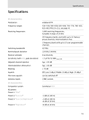
... ranges Receiving frequencies Switching bandwidth Nominal/peak deviation Receiver principle Sensitivity (with HDX, peak deviation) Adjacent channel rejection Intermodulation attenuation Blocking Squelch Pilot tone squelch Antenna inputs AF characteristics Compander system EQ presets Preset 1: "Flat" Preset 2: "Low Cut" Preset 3: "Low Cut/High boost" Preset 4: "High Boost" wideband FM 516-...≥ 65 dB ≥ 70 dB Off, Low: 5 dBμV, Middle: 15 dBμV, High: 25 dBμV can be switched off 2 BNC sockets Sennheiser HDX -3 dB at 180 Hz -3 dB at 180 Hz +6 dB at 10 kHz +6 dB at 10 kHz 51
... ranges Receiving frequencies Switching bandwidth Nominal/peak deviation Receiver principle Sensitivity (with HDX, peak deviation) Adjacent channel rejection Intermodulation attenuation Blocking Squelch Pilot tone squelch Antenna inputs AF characteristics Compander system EQ presets Preset 1: "Flat" Preset 2: "Low Cut" Preset 3: "Low Cut/High boost" Preset 4: "High Boost" wideband FM 516-...≥ 65 dB ≥ 70 dB Off, Low: 5 dBμV, Middle: 15 dBμV, High: 25 dBμV can be switched off 2 BNC sockets Sennheiser HDX -3 dB at 180 Hz -3 dB at 180 Hz +6 dB at 10 kHz +6 dB at 10 kHz 51

Instructions for Use
Page 56
... determined by turning the equipment off and on, the user is subject to correct the interference by Sennheiser electronic Corp. Operation is encouraged to try to the following measures: • Reorient or relocate the receiving antenna. • Increase the separation between the equipment and receiver. • Connect the equipment into operation, please...
... determined by turning the equipment off and on, the user is subject to correct the interference by Sennheiser electronic Corp. Operation is encouraged to try to the following measures: • Reorient or relocate the receiving antenna. • Increase the separation between the equipment and receiver. • Connect the equipment into operation, please...
Instructions for Use
Page 57
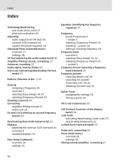
... squelch threshold (Squelch) 33 Advanced Menu (extended menu) overview 27 settings 38 AF Out (adjusting the audio output level) 36 Amplifier/Mixing console, connecting 17 Antennas, mounting 13 Audio signal, muting (Mute) 23 Auto Lock (activating/deactivating the lock mode) 37 B Buttons (function of the ~) 25 C Channel assigning a frequency 39 overview...
... squelch threshold (Squelch) 33 Advanced Menu (extended menu) overview 27 settings 38 AF Out (adjusting the audio output level) 36 Amplifier/Mixing console, connecting 17 Antennas, mounting 13 Audio signal, muting (Mute) 23 Auto Lock (activating/deactivating the lock mode) 37 B Buttons (function of the ~) 25 C Channel assigning a frequency 39 overview...

Instructions for Use
Page 58
Index Mounting antennas 13 receiver 11 Multi-channel operation 43 Mute (muting the audio signal) 23 Muting (audio signal) 23 N Name (entering a name) 36 O Operating menu, using 28 P ...
Index Mounting antennas 13 receiver 11 Multi-channel operation 43 Mute (muting the audio signal) 23 Muting (audio signal) 23 N Name (entering a name) 36 O Operating menu, using 28 P ...