
Instructions for Use
Page 2
.../mixing console 17 Connecting the mains unit ...18 Using the receiver ...19 Switching the receiver on our website at www.sennheiser.com. 1 Contents Contents Important safety instructions ...2 The EM 100 G3 stationary receiver ...4 Areas of application ...4 The frequency bank system ...5 Delivery includes ...7 Product overview ...8 Overview of the EM 100 G3 receiver 8 Overview of the operating menu ...26 Working with the operating...
.../mixing console 17 Connecting the mains unit ...18 Using the receiver ...19 Switching the receiver on our website at www.sennheiser.com. 1 Contents Contents Important safety instructions ...2 The EM 100 G3 stationary receiver ...4 Areas of application ...4 The frequency bank system ...5 Delivery includes ...7 Product overview ...8 Overview of the EM 100 G3 receiver 8 Overview of the operating menu ...26 Working with the operating...
Instructions for Use
Page 5
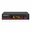
... this series, Sennheiser offers high-quality state-of-the-art RF transmission systems with a high level of operational reliability and ease of the evolution wireless series generation 3 (ew G3). The EM 100 G3 stationary receiver The EM 100 G3 stationary receiver This receiver is part of use. Features of the evolution wireless 100 G3 series: •... bandwidth of 42 MHz • Scan function (Easy Setup) for scanning the frequency banks for unused channels Receiver EM 100 G3 20.12 PEAK 40 0 ew100 G3 533.875 30 -10 20 -20 10 -30 MHz P -40 RF AF MUTE SET Areas of application The...
... this series, Sennheiser offers high-quality state-of-the-art RF transmission systems with a high level of operational reliability and ease of the evolution wireless series generation 3 (ew G3). The EM 100 G3 stationary receiver The EM 100 G3 stationary receiver This receiver is part of use. Features of the evolution wireless 100 G3 series: •... bandwidth of 42 MHz • Scan function (Easy Setup) for scanning the frequency banks for unused channels Receiver EM 100 G3 20.12 PEAK 40 0 ew100 G3 533.875 30 -10 20 -20 10 -30 MHz P -40 RF AF MUTE SET Areas of application The...
Instructions for Use
Page 6
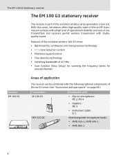
The EM 100 G3 stationary receiver The devices are equipped with the same frequency bank system with up to 12 channels each: Frequency bank 1 ... 20 Channel 1 - An advantage of the factory-... Range 734 - 776 Range Range 780 - 822 823 - 865 Each frequency range (A-E, G) offers 21 frequency banks with factory-preset frequencies. The frequency bank system The receiver is ready for immediate use after switch-on, • several transmission systems can be operated simultaneously on the preset frequencies without causing intermodulation interference. freely...
The EM 100 G3 stationary receiver The devices are equipped with the same frequency bank system with up to 12 channels each: Frequency bank 1 ... 20 Channel 1 - An advantage of the factory-... Range 734 - 776 Range Range 780 - 822 823 - 865 Each frequency range (A-E, G) offers 21 frequency banks with factory-preset frequencies. The frequency bank system The receiver is ready for immediate use after switch-on, • several transmission systems can be operated simultaneously on the preset frequencies without causing intermodulation interference. freely...

Instructions for Use
Page 7
... frequency information sheet. The factory-preset frequencies within one frequency bank are not intermodulation-free (see page 44). 6 These frequencies cannot be downloaded from the EM 100 G3 product page on our website at www.sennheiser.com. The EM 100 G3 stationary receiver Each of the frequency presets, please refer to freely select and store frequencies.
... frequency information sheet. The factory-preset frequencies within one frequency bank are not intermodulation-free (see page 44). 6 These frequencies cannot be downloaded from the EM 100 G3 product page on our website at www.sennheiser.com. The EM 100 G3 stationary receiver Each of the frequency presets, please refer to freely select and store frequencies.
Instructions for Use
Page 8
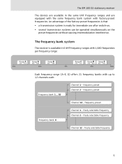
Delivery includes Delivery includes The packaging contains the following items: 1 EM 100 G3 stationary receiver 1 NT 2-3 or NT 2-1 mains unit with one country adapter 2 rod antennas 2 stacking elements 1 instruction manual 1 frequency information sheet 4 device feet 7
Delivery includes Delivery includes The packaging contains the following items: 1 EM 100 G3 stationary receiver 1 NT 2-3 or NT 2-1 mains unit with one country adapter 2 rod antennas 2 stacking elements 1 instruction manual 1 frequency information sheet 4 device feet 7

Instructions for Use
Page 9
... elements - rear panel ¶ Cable grip for power supply DC cable º DC socket (DC IN) for connection of the EM 100 G3 receiver ³· » ¿ ´² A PEAK 20.12 ew100 G3 533.875 40 0 P 25 10 -10 -20 -30 RF AF MHz SET B XXXXXXX 0682 ƹ ƺ A Operating elements - front panel...
... elements - rear panel ¶ Cable grip for power supply DC cable º DC socket (DC IN) for connection of the EM 100 G3 receiver ³· » ¿ ´² A PEAK 20.12 ew100 G3 533.875 40 0 P 25 10 -10 -20 -30 RF AF MHz SET B XXXXXXX 0682 ƹ ƺ A Operating elements - front panel...
Instructions for Use
Page 10
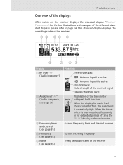
... audio level shows full deflection, the audio level is shown inverted. This standard display displays the operating states of the receiver. 533.875 40 25 10 RF PEAK 0 20.12 -10 ew100 G3 MHz -20 -30 AF P MUTE ቧ ቨ ቩቪ Display ቢ RF level "RF" (Radio Frequency)...) Meaning Diversity display: Antenna input I is active 40 Antenna input II is active 25 10 RF signal level: RF Field strength of the received signal Squelch threshold level PEAK 0 -10 -20 -30 AF Modulation of the transmitter with peak hold function When the display for extended periods...
... audio level shows full deflection, the audio level is shown inverted. This standard display displays the operating states of the receiver. 533.875 40 25 10 RF PEAK 0 20.12 -10 ew100 G3 MHz -20 -30 AF P MUTE ቧ ቨ ቩቪ Display ቢ RF level "RF" (Radio Frequency)...) Meaning Diversity display: Antenna input I is active 40 Antenna input II is active 25 10 RF signal level: RF Field strength of the received signal Squelch threshold level PEAK 0 -10 -20 -30 AF Modulation of the transmitter with peak hold function When the display for extended periods...
Instructions for Use
Page 12
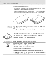
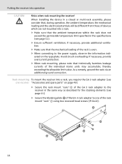
... the stacking elements The stacking elements are designed to set up the receiver on a flat surface Risk of staining of staining. ̈ Do not place the receiver on page 13. If you want to stack your receivers. 11 Therefore, fasten the stacking elements, even if you can mount...even under difficult conditions, we cannot rule out the possibility of furniture surfaces! CAUTION! Setting up the receiver on page 49). if the receiver is dropped. When mounting more than one receiver into a rack, you want to the front of the synthetics used by using antenna splitters (see ...
... the stacking elements The stacking elements are designed to set up the receiver on a flat surface Risk of staining of staining. ̈ Do not place the receiver on page 13. If you want to stack your receivers. 11 Therefore, fasten the stacking elements, even if you can mount...even under difficult conditions, we cannot rule out the possibility of furniture surfaces! CAUTION! Setting up the receiver on page 49). if the receiver is dropped. When mounting more than one receiver into a rack, you want to the front of the synthetics used by using antenna splitters (see ...
Instructions for Use
Page 13
...Secure the stack against toppling over. ̈ Fasten the stacking elements as shown. ̈ Place the receiver on a flat, horizontal surface. Putting the receiver into a 19" rack. ̈ Clean the base of the receiver where you want to fix the device feet. ̈ Fit the device feet to toppling... receiver stacks! High receiver stacks can stack several receivers on each other . 12 Do not fit the device feet when mounting the receiver into operation To fasten the stacking elements ƻ: ̈ Unscrew and remove ...
...Secure the stack against toppling over. ̈ Fasten the stacking elements as shown. ̈ Place the receiver on a flat, horizontal surface. Putting the receiver into a 19" rack. ̈ Clean the base of the receiver where you want to fix the device feet. ̈ Fit the device feet to toppling... receiver stacks! High receiver stacks can stack several receivers on each other . 12 Do not fit the device feet when mounting the receiver into operation To fasten the stacking elements ƻ: ̈ Unscrew and remove ...
Instructions for Use
Page 14
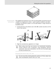
... Ƽ can be used without a large amount of the receiver. ƻ EM 100 0682 FTISIDCERR:EREU2N.Q0ENT9..ODR9N.AIA:OV-N.E: RGXXSXXEXIXX-TXXXYXXXXRXXXXEXXX:CXXEXXIXVXER- a wireless transmission system is to the BNC sockets Ƹ and ƺ at www.sennheiser.com. When using more information, visit the ew G3 product page at the rear of installation work. ̈...
... Ƽ can be used without a large amount of the receiver. ƻ EM 100 0682 FTISIDCERR:EREU2N.Q0ENT9..ODR9N.AIA:OV-N.E: RGXXSXXEXIXX-TXXXYXXXXRXXXXEXXX:CXXEXXIXVXER- a wireless transmission system is to the BNC sockets Ƹ and ƺ at www.sennheiser.com. When using more information, visit the ew G3 product page at the rear of installation work. ̈...
Instructions for Use
Page 15
...ƿ 14 if necessary, provide additional ventilation. ̈ Make sure that intrinsically harmless leakage currents of the GA 3 rack adapter to the receiver in the specifications (see page 51). ̈ Ensure sufficient ventilation; Avoid circuit overloading. As a remedy, ground the rack via an additional ...ground connection. Risks when rack mounting the receiver! Rack mounting To mount the receiver into operation CAUTION! Putting the receiver into a rack, you require the GA 3 rack adapter (see one of the GA 3 rack adapter...
...ƿ 14 if necessary, provide additional ventilation. ̈ Make sure that intrinsically harmless leakage currents of the GA 3 rack adapter to the receiver in the specifications (see page 51). ̈ Ensure sufficient ventilation; Avoid circuit overloading. As a remedy, ground the rack via an additional ...ground connection. Risks when rack mounting the receiver! Rack mounting To mount the receiver into operation CAUTION! Putting the receiver into a rack, you require the GA 3 rack adapter (see one of the GA 3 rack adapter...
Instructions for Use
Page 16
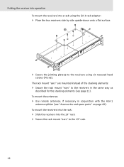
... rack mount "ears" ƿ to the blanking plate . ƻ ƿ ƿ When using more information, visit the ew G3 product page at www.sennheiser.com. Putting the receiver into a 19" rack: ̈ Slide the receiver with the AM 2 antenna front mount kit and an additional GA 3 rack adapter (see "Accessories and spare parts" on...
... rack mount "ears" ƿ to the blanking plate . ƻ ƿ ƿ When using more information, visit the ew G3 product page at www.sennheiser.com. Putting the receiver into a 19" rack: ̈ Slide the receiver with the AM 2 antenna front mount kit and an additional GA 3 rack adapter (see "Accessories and spare parts" on...
Instructions for Use
Page 17
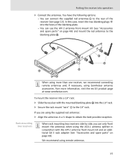
... by side upside-down onto a flat surface. ̈ Secure the jointing plate to the receivers using six recessed head screws (M 3x6). To mount the antennas: ̈ Use remote antennas, if necessary in the same way as described for the stacking ...elements (see "Accessories and spare parts" on page 49). Putting the receiver into operation To mount the receivers into the 19" rack. ̈ Secure the rack mount "ears" to the 19" rack. 16 The rack mount "ears" are mounted instead...
... by side upside-down onto a flat surface. ̈ Secure the jointing plate to the receivers using six recessed head screws (M 3x6). To mount the antennas: ̈ Use remote antennas, if necessary in the same way as described for the stacking ...elements (see "Accessories and spare parts" on page 49). Putting the receiver into operation To mount the receivers into the 19" rack. ̈ Secure the rack mount "ears" to the 19" rack. 16 The rack mount "ears" are mounted instead...
Instructions for Use
Page 18
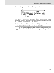
amplifier, mixing console) to the receiver. ̈ Use a suitable cable to connect the amplifier/mixing console to simultaneously connect two devices (e.g. Putting the receiver into operation Connecting an amplifier/mixing console The receiver's ¼" (6.3 mm) jack socket µ and XLR-3M socket ¾ are connected in parallel, allowing you to the ¼" (6.3 mm) jack socket µ or the XLR-3M socket ¾. For detailed information on balanced and unbalanced connection, please refer to the chapter "Connector assignment" on page 53. 17
amplifier, mixing console) to the receiver. ̈ Use a suitable cable to connect the amplifier/mixing console to simultaneously connect two devices (e.g. Putting the receiver into operation Connecting an amplifier/mixing console The receiver's ¼" (6.3 mm) jack socket µ and XLR-3M socket ¾ are connected in parallel, allowing you to the ¼" (6.3 mm) jack socket µ or the XLR-3M socket ¾. For detailed information on balanced and unbalanced connection, please refer to the chapter "Connector assignment" on page 53. 17
Instructions for Use
Page 19
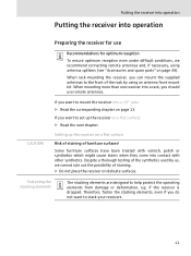
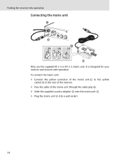
Putting the receiver into a wall socket. 18 It is designed for your receiver and ensures safe operation. To connect the mains unit: ̈ Connect the yellow connector of the mains unit ƽ to the yellow socket º at the rear of the receiver. ̈ Pass the cable of the mains unit through the cable grip ¶. ̈ Slide the supplied country adapter ƾ onto the mains unit ƽ. ̈ Plug the mains unit ƽ into operation Connecting the mains unit ¶ º ƾ ƽ Only use the supplied NT 2-3 or NT 2-1 mains unit.
Putting the receiver into a wall socket. 18 It is designed for your receiver and ensures safe operation. To connect the mains unit: ̈ Connect the yellow connector of the mains unit ƽ to the yellow socket º at the rear of the receiver. ̈ Pass the cable of the mains unit through the cable grip ¶. ̈ Slide the supplied country adapter ƾ onto the mains unit ƽ. ̈ Plug the mains unit ƽ into operation Connecting the mains unit ¶ º ƾ ƽ Only use the supplied NT 2-3 or NT 2-1 mains unit.
Instructions for Use
Page 20
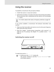
...necessary, the chapter "If a problem occurs ..." It is established and the receiver's RF level display "RF" reacts. The receiver switches on page 47. on and the "Receiver Parameters" standard display appears. 19 Using the receiver Using the receiver To establish a transmission link, proceed as follows: 1. Switch the transmitter ... and receiver are set to the same frequency bank and to observe the notes on frequency selection on : ̈ Briefly press the STANDBY button ². Switching the receiver on/off 533.875 PEAK 40 0 20.12 P 25 10 -10 -20 -30 RF AF ew100 G3 MHz ...
...necessary, the chapter "If a problem occurs ..." It is established and the receiver's RF level display "RF" reacts. The receiver switches on page 47. on and the "Receiver Parameters" standard display appears. 19 Using the receiver Using the receiver To establish a transmission link, proceed as follows: 1. Switch the transmitter ... and receiver are set to the same frequency bank and to observe the notes on frequency selection on : ̈ Briefly press the STANDBY button ². Switching the receiver on/off 533.875 PEAK 40 0 20.12 P 25 10 -10 -20 -30 RF AF ew100 G3 MHz ...

Instructions for Use
Page 21
... to the transmitter: Setting Transferred parameters "Frequency Preset" Currently set frequency "Name" Freely selectable name currently set on the receiver "Pilot Tone" Current pilot tone setting of the ew 100 G3 series with the receiver. When in the operating menu, pressing the STANDBY button ² will cancel your entry (ESC function) and return you...
... to the transmitter: Setting Transferred parameters "Frequency Preset" Currently set frequency "Name" Freely selectable name currently set on the receiver "Pilot Tone" Current pilot tone setting of the ew 100 G3 series with the receiver. When in the operating menu, pressing the STANDBY button ² will cancel your entry (ESC function) and return you...
Instructions for Use
Page 22
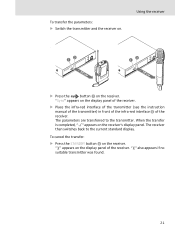
...transmitter. When the transfer is completed, " " appears on the display panel of the receiver. " " also appears if no suitable transmitter was found. 21 " " appears on the receiver's display panel. "Sync" appears on the receiver. To cancel the transfer: ̈ Press the STANDBY button ² on the ...display panel of the receiver. ̈ Place the infra-red interface of the transmitter (see the...
...transmitter. When the transfer is completed, " " appears on the display panel of the receiver. " " also appears if no suitable transmitter was found. 21 " " appears on the receiver's display panel. "Sync" appears on the receiver. To cancel the transfer: ̈ Press the STANDBY button ² on the ...display panel of the receiver. ̈ Place the infra-red interface of the transmitter (see the...
Instructions for Use
Page 23
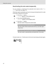
SET ̈ Press the SET button. The lock mode icon ቪ flashes prior to operate the receiver: SET ̈ Press the SET button. If the lock mode is automatically activated after 10 seconds. "Locked" appears on the display panel. appears on the ... lock mode remains deactivated until you have to temporarily deactivate it In order to be able to the lock mode being activated again. Using the receiver Deactivating the lock mode temporarily You can activate or deactivate the automatic lock mode via the "Auto Lock" menu item (see page 37). PEAK 20...
SET ̈ Press the SET button. The lock mode icon ቪ flashes prior to operate the receiver: SET ̈ Press the SET button. If the lock mode is automatically activated after 10 seconds. "Locked" appears on the display panel. appears on the ... lock mode remains deactivated until you have to temporarily deactivate it In order to be able to the lock mode being activated again. Using the receiver Deactivating the lock mode temporarily You can activate or deactivate the automatic lock mode via the "Auto Lock" menu item (see page 37). PEAK 20...
Instructions for Use
Page 24
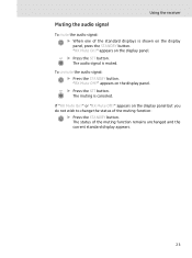
... or "RX Mute Off?" "RX Mute Off?" SET ̈ Press the SET button. To unmute the audio signal: ̈ Press the STANDBY button. Using the receiver Muting the audio signal To mute the audio signal: ̈ When one of the standard displays is shown on the display panel. appears on the...
... or "RX Mute Off?" "RX Mute Off?" SET ̈ Press the SET button. To unmute the audio signal: ̈ Press the STANDBY button. Using the receiver Muting the audio signal To mute the audio signal: ̈ When one of the standard displays is shown on the display panel. appears on the...