
Instructions for Use
Page 1
EM 100 Instruction manual
EM 100 Instruction manual

Instructions for Use
Page 2
... a problem occurs ...47 Accessories and spare parts ...49 Specifications ...51 Manufacturer Declarations ...54 Index ...56 An animated instruction manual can be viewed on the EM 100 G3 product page on /off ...19 Synchronizing a transmitter with the receiver 20 Deactivating the lock mode temporarily 22 Muting the audio signal ...23 Selecting a standard ......11 Connecting an amplifier/mixing console 17 Connecting the mains unit ...18 Using the receiver ...19 Switching the receiver on our website at www.sennheiser.com. 1 individual operation 42 Synchronizing transmitters with the receiver -
... a problem occurs ...47 Accessories and spare parts ...49 Specifications ...51 Manufacturer Declarations ...54 Index ...56 An animated instruction manual can be viewed on the EM 100 G3 product page on /off ...19 Synchronizing a transmitter with the receiver 20 Deactivating the lock mode temporarily 22 Muting the audio signal ...23 Selecting a standard ......11 Connecting an amplifier/mixing console 17 Connecting the mains unit ...18 Using the receiver ...19 Switching the receiver on our website at www.sennheiser.com. 1 individual operation 42 Synchronizing transmitters with the receiver -
Instructions for Use
Page 3
Always include this instruction manual when passing the product on the product. • Only use attachments/accessories specified by Sennheiser. 2 during lightning storms or - in order to direct sunlight for longer periods of time. • Only operate the mains unit from the mains, - only operated ...
Always include this instruction manual when passing the product on the product. • Only use attachments/accessories specified by Sennheiser. 2 during lightning storms or - in order to direct sunlight for longer periods of time. • Only operate the mains unit from the mains, - only operated ...
Instructions for Use
Page 4
... producing sound pressure exceeding 85 dB(A). 85 dB(A) is by Sennheiser or those described herein. 3 The following are required, be shortened in your ears. • You have the impression (even for the duration of industrial medicine. "Improper use of the ew 100 G3 series products includes: • having the same characteristics as a basis...
... producing sound pressure exceeding 85 dB(A). 85 dB(A) is by Sennheiser or those described herein. 3 The following are required, be shortened in your ears. • You have the impression (even for the duration of industrial medicine. "Improper use of the ew 100 G3 series products includes: • having the same characteristics as a basis...
Instructions for Use
Page 5
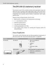
... be combined with the following optional components of the ew G3 series (see "Accessories and spare parts" on page 49): Transmitters SK 100 G3 SKM 100 G3 Combinable with studioquality sound. The EM 100 G3 stationary receiver The EM 100 G3 stationary receiver This receiver is part of use. With this series, Sennheiser offers high-quality state-of-the-art RF transmission...
... be combined with the following optional components of the ew G3 series (see "Accessories and spare parts" on page 49): Transmitters SK 100 G3 SKM 100 G3 Combinable with studioquality sound. The EM 100 G3 stationary receiver The EM 100 G3 stationary receiver This receiver is part of use. With this series, Sennheiser offers high-quality state-of-the-art RF transmission...
Instructions for Use
Page 6
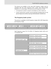
frequency preset Frequency bank U Channel 1 - The EM 100 G3 stationary receiver The devices are available in 6 UHF frequency ranges with 1,680 frequencies per frequency range: Range 516 - 558 Range 566 - 608 Range 626 - 668 ...
frequency preset Frequency bank U Channel 1 - The EM 100 G3 stationary receiver The devices are available in 6 UHF frequency ranges with 1,680 frequencies per frequency range: Range 516 - 558 Range 566 - 608 Range 626 - 668 ...

Instructions for Use
Page 7
... receiver Each of the frequency information sheet can be downloaded from the EM 100 G3 product page on our website at www.sennheiser.com. Updated versions of the channels in the frequency banks "1" to "20" has been factorypreset to a fixed frequency (frequency preset). These frequencies cannot be that ...
... receiver Each of the frequency information sheet can be downloaded from the EM 100 G3 product page on our website at www.sennheiser.com. Updated versions of the channels in the frequency banks "1" to "20" has been factorypreset to a fixed frequency (frequency preset). These frequencies cannot be that ...
Instructions for Use
Page 8
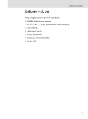
Delivery includes Delivery includes The packaging contains the following items: 1 EM 100 G3 stationary receiver 1 NT 2-3 or NT 2-1 mains unit with one country adapter 2 rod antennas 2 stacking elements 1 instruction manual 1 frequency information sheet 4 device feet 7
Delivery includes Delivery includes The packaging contains the following items: 1 EM 100 G3 stationary receiver 1 NT 2-3 or NT 2-1 mains unit with one country adapter 2 rod antennas 2 stacking elements 1 instruction manual 1 frequency information sheet 4 device feet 7

Instructions for Use
Page 9
... elements - rear panel ¶ Cable grip for power supply DC cable º DC socket (DC IN) for connection of the EM 100 G3 receiver ³· » ¿ ´² A PEAK 20.12 ew100 G3 533.875 40 0 P 25 10 -10 -20 -30 RF AF MHz SET B XXXXXXX 0682 ƹ ƺ A Operating elements - Product...
... elements - rear panel ¶ Cable grip for power supply DC cable º DC socket (DC IN) for connection of the EM 100 G3 receiver ³· » ¿ ´² A PEAK 20.12 ew100 G3 533.875 40 0 P 25 10 -10 -20 -30 RF AF MHz SET B XXXXXXX 0682 ƹ ƺ A Operating elements - Product...
Instructions for Use
Page 10
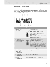
... periods of the receiver 9 This standard display displays the operating states of the receiver. 533.875 40 25 10 RF PEAK 0 20.12 -10 ew100 G3 MHz -20 -30 AF P MUTE ቧ ቨ ቩቪ Display ቢ RF level "RF" (Radio Frequency) ባ Audio level "AF" (Audio Frequency, see page 36...
... periods of the receiver 9 This standard display displays the operating states of the receiver. 533.875 40 25 10 RF PEAK 0 20.12 -10 ew100 G3 MHz -20 -30 AF P MUTE ቧ ቨ ቩቪ Display ቢ RF level "RF" (Radio Frequency) ባ Audio level "AF" (Audio Frequency, see page 36...
Instructions for Use
Page 11
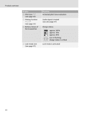
charge status is critical Lock mode is flashing; Product overview Display ቧ Pilot tone "P" (see page 40) ቨ Muting function "MUTE" (see page 23) ቩ Battery status of the transmitter ቪ Lock mode icon (see page 37) Meaning Activated pilot tone evaluation Audio signal is muted (see also page 47) Charge status: approx. 100% approx. 70% approx. 30% icon is activated 10
charge status is critical Lock mode is flashing; Product overview Display ቧ Pilot tone "P" (see page 40) ቨ Muting function "MUTE" (see page 23) ቩ Battery status of the transmitter ቪ Lock mode icon (see page 37) Meaning Activated pilot tone evaluation Audio signal is muted (see also page 47) Charge status: approx. 100% approx. 70% approx. 30% icon is activated 10
Instructions for Use
Page 12
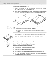
if the receiver is dropped. Some furniture surfaces have been treated with varnish, polish or synthetics which might cause stains when they come into a rack, you should use Recommendations for optimum reception To ensure optimum reception even under difficult conditions, we cannot rule out the possibility of furniture surfaces! Setting up the receiver on page 49). Despite a thorough testing of the synthetics used by using antenna splitters (see "Accessories and spare parts" on a flat surface: ̈ Read the next chapter. Therefore, fasten the stacking elements, even if...
if the receiver is dropped. Some furniture surfaces have been treated with varnish, polish or synthetics which might cause stains when they come into a rack, you should use Recommendations for optimum reception To ensure optimum reception even under difficult conditions, we cannot rule out the possibility of furniture surfaces! Setting up the receiver on page 49). Despite a thorough testing of the synthetics used by using antenna splitters (see "Accessories and spare parts" on a flat surface: ̈ Read the next chapter. Therefore, fasten the stacking elements, even if...
Instructions for Use
Page 13
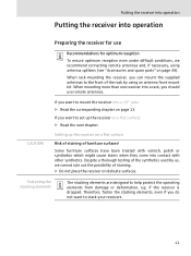
Do not fit the device feet when mounting the receiver into operation To fasten the stacking elements ƻ: ̈ Unscrew and remove the two recessed head screws (M4x8) on each side of the receiver (see left-hand diagram). ̈ Secure the stacking elements ƻ to the sides of the receiver using the previously removed recessed head screws (see right-hand diagram). ƻ Fitting the device feet If you want to stack receivers (see next section), only fit the device feet to the base of the lowermost receiver. CAUTION! High receiver stacks can stack several receivers on top of ...
Do not fit the device feet when mounting the receiver into operation To fasten the stacking elements ƻ: ̈ Unscrew and remove the two recessed head screws (M4x8) on each side of the receiver (see left-hand diagram). ̈ Secure the stacking elements ƻ to the sides of the receiver using the previously removed recessed head screws (see right-hand diagram). ƻ Fitting the device feet If you want to stack receivers (see next section), only fit the device feet to the base of the lowermost receiver. CAUTION! High receiver stacks can stack several receivers on top of ...
Instructions for Use
Page 14
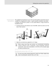
...using more information, visit the ew G3 product page at the rear of the receiver. ƻ EM 100 0682 FTISIDCERR:EREU2N.Q0ENT9..ODR9N.AIA:OV-N.E: RGXXSXXEXIXX-TXXXYXXXXRXXXXEXXX:CXXEXXIXVXER- XXX MHz DESIGNED IN GERMANY, ASSEMBLED IN USA Ƹ ƺ EM 100 0682 FTISIDCERR:EREU2N.Q0ENT9..ODR9N.AIA:...rod antennas Ƽ to the BNC sockets Ƹ and ƺ at www.sennheiser.com. Fore more than one receiver, we recommend connecting remote antennas and, if necessary, using Sennheiser antenna accessories. a wireless transmission system is to be mounted quickly and easily and...
...using more information, visit the ew G3 product page at the rear of the receiver. ƻ EM 100 0682 FTISIDCERR:EREU2N.Q0ENT9..ODR9N.AIA:OV-N.E: RGXXSXXEXIXX-TXXXYXXXXRXXXXEXXX:CXXEXXIXVXER- XXX MHz DESIGNED IN GERMANY, ASSEMBLED IN USA Ƹ ƺ EM 100 0682 FTISIDCERR:EREU2N.Q0ENT9..ODR9N.AIA:...rod antennas Ƽ to the BNC sockets Ƹ and ƺ at www.sennheiser.com. Fore more than one receiver, we recommend connecting remote antennas and, if necessary, using Sennheiser antenna accessories. a wireless transmission system is to be mounted quickly and easily and...
Instructions for Use
Page 15
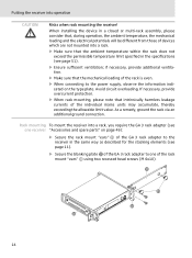
Avoid circuit overloading. If necessary, provide overcurrent protection. ̈ When rack mounting, please note that the ambient temperature within the rack does not exceed the permissible temperature limit specified in the specifications (see page 51). ̈ Ensure sufficient ventilation; As a remedy, ground the rack via an additional ground connection. When installing the device in the same way as described for the stacking elements (see one receiver "Accessories and spare parts" on the type plate. Rack mounting To mount the receiver into a rack, you require the GA 3 rack adapter ...
Avoid circuit overloading. If necessary, provide overcurrent protection. ̈ When rack mounting, please note that the ambient temperature within the rack does not exceed the permissible temperature limit specified in the specifications (see page 51). ̈ Ensure sufficient ventilation; As a remedy, ground the rack via an additional ground connection. When installing the device in the same way as described for the stacking elements (see one receiver "Accessories and spare parts" on the type plate. Rack mounting To mount the receiver into a rack, you require the GA 3 rack adapter ...
Instructions for Use
Page 16
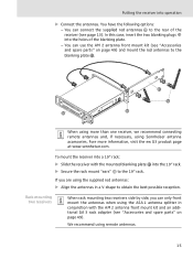
... a V-shape to the blanking plate . ƻ ƿ ƿ When using more information, visit the ew G3 product page at www.sennheiser.com. Fore more than one receiver, we recommend connecting remote antennas and, if necessary, using Sennheiser antenna accessories. If you can connect the supplied rod antennas Ƽ to the 19" rack. In...
... a V-shape to the blanking plate . ƻ ƿ ƿ When using more information, visit the ew G3 product page at www.sennheiser.com. Fore more than one receiver, we recommend connecting remote antennas and, if necessary, using Sennheiser antenna accessories. If you can connect the supplied rod antennas Ƽ to the 19" rack. In...
Instructions for Use
Page 17
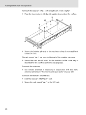
The rack mount "ears" are mounted instead of the stacking elements: ̈ Secure the rack mount "ears" to the 19" rack. 16 To mount the antennas: ̈ Use remote antennas, if necessary in the same way as described for the stacking elements (see "Accessories and spare parts" on page 49). To mount the receivers into the rack: ̈ Slide the receivers into a rack using the GA 3 rack adapter: ̈ Place the two receivers side by side upside-down onto a flat surface. ̈ Secure the jointing plate to the receivers using six recessed head screws (M 3x6). Putting the receiver into ...
The rack mount "ears" are mounted instead of the stacking elements: ̈ Secure the rack mount "ears" to the 19" rack. 16 To mount the antennas: ̈ Use remote antennas, if necessary in the same way as described for the stacking elements (see "Accessories and spare parts" on page 49). To mount the receivers into the rack: ̈ Slide the receivers into a rack using the GA 3 rack adapter: ̈ Place the two receivers side by side upside-down onto a flat surface. ̈ Secure the jointing plate to the receivers using six recessed head screws (M 3x6). Putting the receiver into ...
Instructions for Use
Page 18
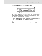
For detailed information on balanced and unbalanced connection, please refer to the ¼" (6.3 mm) jack socket µ or the XLR-3M socket ¾. amplifier, mixing console) to the receiver. ̈ Use a suitable cable to connect the amplifier/mixing console to the chapter "Connector assignment" on page 53. 17 Putting the receiver into operation Connecting an amplifier/mixing console The receiver's ¼" (6.3 mm) jack socket µ and XLR-3M socket ¾ are connected in parallel, allowing you to simultaneously connect two devices (e.g.
For detailed information on balanced and unbalanced connection, please refer to the ¼" (6.3 mm) jack socket µ or the XLR-3M socket ¾. amplifier, mixing console) to the receiver. ̈ Use a suitable cable to connect the amplifier/mixing console to the chapter "Connector assignment" on page 53. 17 Putting the receiver into operation Connecting an amplifier/mixing console The receiver's ¼" (6.3 mm) jack socket µ and XLR-3M socket ¾ are connected in parallel, allowing you to simultaneously connect two devices (e.g.
Instructions for Use
Page 19
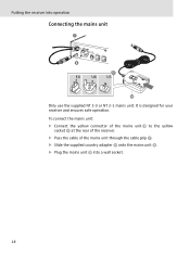
To connect the mains unit: ̈ Connect the yellow connector of the mains unit ƽ to the yellow socket º at the rear of the receiver. ̈ Pass the cable of the mains unit through the cable grip ¶. ̈ Slide the supplied country adapter ƾ onto the mains unit ƽ. ̈ Plug the mains unit ƽ into operation Connecting the mains unit ¶ º ƾ ƽ Only use the supplied NT 2-3 or NT 2-1 mains unit. It is designed for your receiver and ensures safe operation. Putting the receiver into a wall socket. 18
To connect the mains unit: ̈ Connect the yellow connector of the mains unit ƽ to the yellow socket º at the rear of the receiver. ̈ Pass the cable of the mains unit through the cable grip ¶. ̈ Slide the supplied country adapter ƾ onto the mains unit ƽ. ̈ Plug the mains unit ƽ into operation Connecting the mains unit ¶ º ƾ ƽ Only use the supplied NT 2-3 or NT 2-1 mains unit. It is designed for your receiver and ensures safe operation. Putting the receiver into a wall socket. 18
Instructions for Use
Page 20
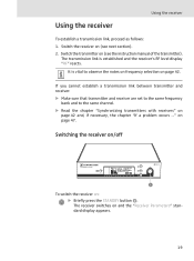
Switching the receiver on/off 533.875 PEAK 40 0 20.12 P 25 10 -10 -20 -30 RF AF ew100 G3 MHz SET ² To switch the receiver on (see the instruction manual of the transmitter). Switch the receiver on : ̈ Briefly press the STANDBY button &#...
Switching the receiver on/off 533.875 PEAK 40 0 20.12 P 25 10 -10 -20 -30 RF AF ew100 G3 MHz SET ² To switch the receiver on (see the instruction manual of the transmitter). Switch the receiver on : ̈ Briefly press the STANDBY button &#...