Brochure Wireless System Manager
Page 7
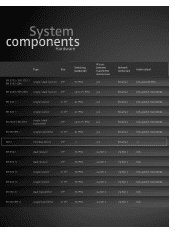
... transmitter ½ 19'' 36 MHz via Net 1 via Net 1 XLR System components Hardware Type Size EM 3731 / EM 3732 / EM 3732-COM single / dual receiver 19'' EM 2000 / EM 2050 single / dual receiver 19'' Switching bandwidth 90 MHz IR-sync between transmitter and receiver yes Network connection Audio output Ethernet XLR and AES-EBU up to 75 MHz yes Ethernet...
... transmitter ½ 19'' 36 MHz via Net 1 via Net 1 XLR System components Hardware Type Size EM 3731 / EM 3732 / EM 3732-COM single / dual receiver 19'' EM 2000 / EM 2050 single / dual receiver 19'' Switching bandwidth 90 MHz IR-sync between transmitter and receiver yes Network connection Audio output Ethernet XLR and AES-EBU up to 75 MHz yes Ethernet...
Instructions for use
Page 2
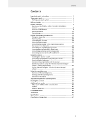
...of the EM 3731-II/EM 3732-II/EM 3732 COM-II receivers ...8 Overview of the displays 9 Reception display 10 Status display 11 Putting the receiver into operation 13 Fitting the device feet 13 Rack mounting 13 Connecting the antennas 14 Daisy chaining receivers 16 Connecting the receiver to the mains/disconnecting the receiver from ...menu 23 Working with the operating menu 24 Overview of the menus 25 Adjustment tips for the operating menu 29 Cleaning the receiver 40 Additional information 41 HiDyn plus™ (HDP) or HDX noise reduction 41 Squelch ...41 Diversity reception 42 If ...
...of the EM 3731-II/EM 3732-II/EM 3732 COM-II receivers ...8 Overview of the displays 9 Reception display 10 Status display 11 Putting the receiver into operation 13 Fitting the device feet 13 Rack mounting 13 Connecting the antennas 14 Daisy chaining receivers 16 Connecting the receiver to the mains/disconnecting the receiver from ...menu 23 Working with the operating menu 24 Overview of the menus 25 Adjustment tips for the operating menu 29 Cleaning the receiver 40 Additional information 41 HiDyn plus™ (HDP) or HDX noise reduction 41 Squelch ...41 Diversity reception 42 If ...
Instructions for use
Page 3
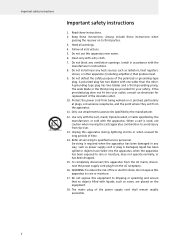
... with a dry cloth. 7. The wide blade or the third prong are placed on the equipment. 18. Follow all warnings. 4. Keep these instructions when passing the receiver on or pinched, particularly at plugs, convenience receptacles, and the point where they exit from being walked on to dripping or splashing and ensure that...
... with a dry cloth. 7. The wide blade or the third prong are placed on the equipment. 18. Follow all warnings. 4. Keep these instructions when passing the receiver on or pinched, particularly at plugs, convenience receptacles, and the point where they exit from being walked on to dripping or splashing and ensure that...
Instructions for use
Page 4
... the impression (even for a short time only) that may result in fire and electric shock. Sennheiser, as the manufacturer, is therefore obliged to the risk of electric shock if the receiver is opened. The symbols on the left is attached to constitute risk of fire or electric shock...longer durations can no user serviceable parts inside. At higher volumes, the duration must be of sufficient magnitude to the rear of the receiver. Overloading Do not overload wall outlets and extension cords as a basis according to the rules and regulations of the trade association responsible...
... the impression (even for a short time only) that may result in fire and electric shock. Sennheiser, as the manufacturer, is therefore obliged to the risk of electric shock if the receiver is opened. The symbols on the left is attached to constitute risk of fire or electric shock...longer durations can no user serviceable parts inside. At higher volumes, the duration must be of sufficient magnitude to the rear of the receiver. Overloading Do not overload wall outlets and extension cords as a basis according to the rules and regulations of the trade association responsible...

Instructions for use
Page 5
Important safety instructions Intended use of the EM 3731-II single receiver or the EM 3732-II and EM 3732 COM-II twin receivers includes: • having read these instructions, or under operating conditions which differ from those described herein. 4 "Improper use of the receiver Intended use " means using the receiver other than as described in these instructions, especially the chapter "Important safety instructions" on page 2, • using the receiver within the operating conditions and limitations described in this instruction manual.
Important safety instructions Intended use of the EM 3731-II single receiver or the EM 3732-II and EM 3732 COM-II twin receivers includes: • having read these instructions, or under operating conditions which differ from those described herein. 4 "Improper use of the receiver Intended use " means using the receiver other than as described in these instructions, especially the chapter "Important safety instructions" on page 2, • using the receiver within the operating conditions and limitations described in this instruction manual.
Instructions for use
Page 6
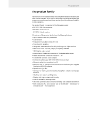
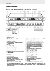
... transmitters • Both receivers of a twin receiver can be monitored - Due to a PC • Receivers can be monitored and remote controlled using the supplied Sennheiser WSM PC software • Operation via headphones 5 The product family is comprised of the following models: • EM 3732 COM-II twin receiver • EM 3732-II twin receiver • EM 3731-II single receiver All receivers of the product family...
... transmitters • Both receivers of a twin receiver can be monitored - Due to a PC • Receivers can be monitored and remote controlled using the supplied Sennheiser WSM PC software • Operation via headphones 5 The product family is comprised of the following models: • EM 3732 COM-II twin receiver • EM 3732-II twin receiver • EM 3731-II single receiver All receivers of the product family...
Instructions for use
Page 7
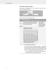
... bank. 6 max. 60 Optimized for maximum transmission reliability U The receiving frequencies can be subject to interference and intermodulation. The product family The frequency bank system The receivers are available in Low Intermodulation mode CAUTION! within the switching bandwidth.... within the frequency banks "1" to "6" are factory- 2 preset (see enclosed frequency table) and cannot be freely selected within the receiver's frequency range - Additionally available channels in four UHF frequency ranges with up to 184 MHz switching bandwidth: Range L 470 - 638...
... bank. 6 max. 60 Optimized for maximum transmission reliability U The receiving frequencies can be subject to interference and intermodulation. The product family The frequency bank system The receivers are available in Low Intermodulation mode CAUTION! within the switching bandwidth.... within the frequency banks "1" to "6" are factory- 2 preset (see enclosed frequency table) and cannot be freely selected within the receiver's frequency range - Additionally available channels in four UHF frequency ranges with up to 184 MHz switching bandwidth: Range L 470 - 638...
Instructions for use
Page 8
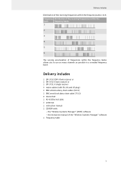
Delivery includes 1 EM 3732 COM-II twin receiver or 1 EM 3732-II twin receiver or 1 EM 3731-II single receiver 3 mains cables (with EU, UK and US plug) 2 BNC antenna daisy chain cables (50 Ω) 1 BNC word clock daisy chain cable ... frequency banks allows you to use as many channels as possible in a crowded frequency band. Delivery includes Distribution of the receiving frequencies within the frequency banks 1 to 6: Frequency Distribution of the receiving frequencies within the bank frequency banks 1 2 3 4 5 6 The varying accumulation of the "Wireless Systems Manager" software...
Delivery includes 1 EM 3732 COM-II twin receiver or 1 EM 3732-II twin receiver or 1 EM 3731-II single receiver 3 mains cables (with EU, UK and US plug) 2 BNC antenna daisy chain cables (50 Ω) 1 BNC word clock daisy chain cable ... frequency banks allows you to use as many channels as possible in a crowded frequency band. Delivery includes Distribution of the receiving frequencies within the frequency banks 1 to 6: Frequency Distribution of the receiving frequencies within the bank frequency banks 1 2 3 4 5 6 The varying accumulation of the "Wireless Systems Manager" software...
Instructions for use
Page 9
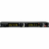
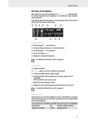
... Ω) S LED for booster supply of antenna input B T Label with hazard warnings U Type plate V Label with frequency range for booster supply of the EM 3731-II/EM 3732-II/EM 3732 COM-II receivers True Diversity Receiver EM 3732-II 776.000 A RF B % DEV M 300 PEAK H z 100 100 30 10 50 01.01BANK CH HD P AF COM μV 10 776.000 A RF B % DEV...
... Ω) S LED for booster supply of antenna input B T Label with hazard warnings U Type plate V Label with frequency range for booster supply of the EM 3731-II/EM 3732-II/EM 3732 COM-II receivers True Diversity Receiver EM 3732-II 776.000 A RF B % DEV M 300 PEAK H z 100 100 30 10 50 01.01BANK CH HD P AF COM μV 10 776.000 A RF B % DEV...
Instructions for use
Page 10
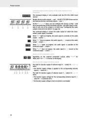
... ¶ "MHz" - The brightness is displayed º 6-step transmitter battery status display ¾ Command display (status display for the audio outputs AF and Command) (EM 3732 COM-II twin receiver only) µ Display for the compander system ¸ Display for the squelch threshold For additional information, refer to page 11. With each new button...
... ¶ "MHz" - The brightness is displayed º 6-step transmitter battery status display ¾ Command display (status display for the audio outputs AF and Command) (EM 3732 COM-II twin receiver only) µ Display for the compander system ¸ Display for the squelch threshold For additional information, refer to page 11. With each new button...
Instructions for use
Page 11
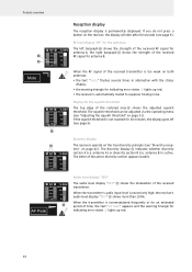
... be adjusted via the operating menu (see "Adjusting the squelch threshold" on page 42). If the squelch threshold is too weak on the receiver, the display will dim after 60 seconds (see "Diversity reception" on page 31). antenna A) or diversity section B (i.e. When the transmitter...'s audio input level is active. antenna B) is excessively high, the receiver's audio level display "DEV" ¿ shows more than 100%. If you do not press a button on both antennas: • the text "Mute"...
... be adjusted via the operating menu (see "Adjusting the squelch threshold" on page 42). If the squelch threshold is too weak on the receiver, the display will dim after 60 seconds (see "Diversity reception" on page 31). antenna A) or diversity section B (i.e. When the transmitter...'s audio input level is active. antenna B) is excessively high, the receiver's audio level display "DEV" ¿ shows more than 100%. If you do not press a button on both antennas: • the text "Mute"...
Instructions for use
Page 12
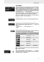
...¸ shows - depending on the selection made in the operating menu, you can be displayed within the status display. With the EM 3732 COM-II receiver, the command display can also be changed in alternation with the operating menu" on the charge status of the transmitter's battery/accupack:... Number of the receiver. approx. 60 % half-full approx. 40 % - either the frequency bank and the channel number or the name of ...
...¸ shows - depending on the selection made in the operating menu, you can be displayed within the status display. With the EM 3732 COM-II receiver, the command display can also be changed in alternation with the operating menu" on the charge status of the transmitter's battery/accupack:... Number of the receiver. approx. 60 % half-full approx. 40 % - either the frequency bank and the channel number or the name of ...
Instructions for use
Page 13
...receiver so that - Product overview Command display (status display of the audio outputs AF and Command) AF COM The command display is only available with the command button of the transmitter pressed - Besides the two audio outputs K and M the EM 3732 COM-II twin receiver also features the two command outputs J and L. with the EM 3732 COM-II... twin receiver.
...receiver so that - Product overview Command display (status display of the audio outputs AF and Command) AF COM The command display is only available with the command button of the transmitter pressed - Besides the two audio outputs K and M the EM 3732 COM-II twin receiver also features the two command outputs J and L. with the EM 3732 COM-II... twin receiver.
Instructions for use
Page 14
...- especially when you are using an extension cable or a multi-outlet power strip. ̈ When installing the receiver in a closed or multi-rack assembly, please consider that the receiver cannot slip on the surface on the type plate. As a remedy, ground the rack via an additional ground... rack. ̈ The ambient temperature within the rack must not exceed the temperature limit specified in the specifications. ̈ When installing the receiver in a closed or multi-rack assembly, please note that intrinsically harmless leakage currents of the device by us, we cannot rule out the ...
...- especially when you are using an extension cable or a multi-outlet power strip. ̈ When installing the receiver in a closed or multi-rack assembly, please consider that the receiver cannot slip on the surface on the type plate. As a remedy, ground the rack via an additional ground... rack. ̈ The ambient temperature within the rack must not exceed the temperature limit specified in the specifications. ̈ When installing the receiver in a closed or multi-rack assembly, please note that intrinsically harmless leakage currents of the device by us, we cannot rule out the ...
Instructions for use
Page 15
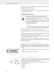
...the two supplied antennas to the front of the rack" on delivery. a wireless transmission system is applied to the rear of the receiver The supplied antennas can produce sparking and audio interference. ̈ Use insulated antennas. The GA 3030 AM consists of the rack when... of short-circuit due to BNC connector [), • 2 antenna holders Z, • 4 screws, • 2 washers Y, • 2 nuts X. 14 Putting the receiver into operation NO P Q RS W Y X The rack mount "ears" are suitable for supplying the antenna signals to the rack using four screws (not included in the...
...the two supplied antennas to the front of the rack" on delivery. a wireless transmission system is applied to the rear of the receiver The supplied antennas can produce sparking and audio interference. ̈ Use insulated antennas. The GA 3030 AM consists of the rack when... of short-circuit due to BNC connector [), • 2 antenna holders Z, • 4 screws, • 2 washers Y, • 2 nuts X. 14 Putting the receiver into operation NO P Q RS W Y X The rack mount "ears" are suitable for supplying the antenna signals to the rack using four screws (not included in the...
Instructions for use
Page 16
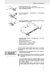
...the handles of the receiver using two of the supplied screws respectively. [ -II \ NO P Q RS ̈ Connect the two BNC connectors [ to the BNC sockets O and R at the rear of the receiver. ̈ Slide the receiver into operation 1 ̈ Unsecure the rack mount "ears" 1 from Sennheiser are available as accessories.... from the rack. ̈ Guide the BNC cables through the holes in the rack mount "ears" as -II shown in a V-shape. A 3700, AD 3700) or antenna boosters (e.g. Putting the receiver into the 19" rack. ̈ Resecure the rack mount "ears" 1 to the rack. ̈ Connect...
...the handles of the receiver using two of the supplied screws respectively. [ -II \ NO P Q RS ̈ Connect the two BNC connectors [ to the BNC sockets O and R at the rear of the receiver. ̈ Slide the receiver into operation 1 ̈ Unsecure the rack mount "ears" 1 from Sennheiser are available as accessories.... from the rack. ̈ Guide the BNC cables through the holes in the rack mount "ears" as -II shown in a V-shape. A 3700, AD 3700) or antenna boosters (e.g. Putting the receiver into the 19" rack. ̈ Resecure the rack mount "ears" 1 to the rack. ̈ Connect...
Instructions for use
Page 17
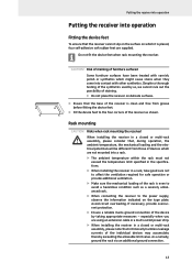
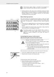
...walls). Maintain a minimum distance of 1 m between antennas and a minimum distance of the external word clock generator. 16 The receiver has no mains switch. To connect the receiver to the mains: ̈ Connect the supplied mains cable to 240 V AC, 50 or 60 Hz). ̈ Ensure... chained using multi-outlet power strips or extension cables. The antenna signals are also daisy chained when a receiver is switched off . If you are interrupted, i.e.: - D To disconnect the receiver from the mains: ̈ Pull out the mains connector from the mains CAUTION! ANT A ANT B...
...walls). Maintain a minimum distance of 1 m between antennas and a minimum distance of the external word clock generator. 16 The receiver has no mains switch. To connect the receiver to the mains: ̈ Connect the supplied mains cable to 240 V AC, 50 or 60 Hz). ̈ Ensure... chained using multi-outlet power strips or extension cables. The antenna signals are also daisy chained when a receiver is switched off . If you are interrupted, i.e.: - D To disconnect the receiver from the mains: ̈ Pull out the mains connector from the mains CAUTION! ANT A ANT B...
Instructions for use
Page 18
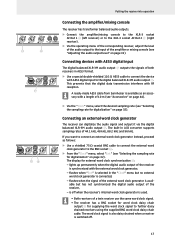
.... is selected in the "Clock" menu but has not synchronized the digital audio output of the receiver, - A ready-made AES3 cable from Sennheiser is connected, - K M G HI Putting the receiver into operation Connecting the amplifier/mixing console The receiver has transformer balanced audio outputs. ̈ Connect the amplifier/mixing console to the XLR-3 socket AF...
.... is selected in the "Clock" menu but has not synchronized the digital audio output of the receiver, - A ready-made AES3 cable from Sennheiser is connected, - K M G HI Putting the receiver into operation Connecting the amplifier/mixing console The receiver has transformer balanced audio outputs. ̈ Connect the amplifier/mixing console to the XLR-3 socket AF...
Instructions for use
Page 19
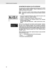
... RJ 45 socket for signals and records the corresponding measured values. Additionally, you can be centrally configured and monitored via Ethernet The receivers can update the firmware in the "Spectrum Analyzer", please note that you require a standard 100Base-T Ethernet switch. ̈ Connect ... on your PC. ̈ Continue as described in the instruction manual of the "Wireless Systems Manager" manual. When selecting this receiver in the receivers. When you are working with the "Wireless Systems Manager" software, you cannot use the "Spectrum Analyzer" tool to the chapter ...
... RJ 45 socket for signals and records the corresponding measured values. Additionally, you can be centrally configured and monitored via Ethernet The receivers can update the firmware in the "Spectrum Analyzer", please note that you require a standard 100Base-T Ethernet switch. ̈ Connect ... on your PC. ̈ Continue as described in the instruction manual of the "Wireless Systems Manager" manual. When selecting this receiver in the receivers. When you are working with the "Wireless Systems Manager" software, you cannot use the "Spectrum Analyzer" tool to the chapter ...

Instructions for use
Page 20
... putting the headphones on : ̈ Press the button C. The receiver is switched off, - Danger of the EM 3732-II or EM 3732 COM-II twin receiver have a common headphone socket 2. The two receivers of hearing damage! If you only want to use one of the two receivers of the EM 3732-II or EM 3732 COM-II, you to either monitor the audio signal of one...
... putting the headphones on : ̈ Press the button C. The receiver is switched off, - Danger of the EM 3732-II or EM 3732 COM-II twin receiver have a common headphone socket 2. The two receivers of hearing damage! If you only want to use one of the two receivers of the EM 3732-II or EM 3732 COM-II, you to either monitor the audio signal of one...
