
Instructions for use
Page 1
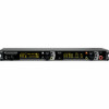
EM 3731-II EM 3732-II EM 3732-II Command Instruction manual
EM 3731-II EM 3732-II EM 3732-II Command Instruction manual

Instructions for use
Page 5
Important safety instructions Intended use of the EM 3731-II single receiver or the EM 3732-II and EM 3732 COM-II twin receivers includes: • having read these instructions, or under operating conditions which differ from those described herein. 4 "Improper use of the receiver Intended use " means using the receiver other than as described in these instructions, especially the chapter "Important safety instructions" on page 2, • using the receiver within the operating conditions and limitations described in this instruction manual.
Important safety instructions Intended use of the EM 3731-II single receiver or the EM 3732-II and EM 3732 COM-II twin receivers includes: • having read these instructions, or under operating conditions which differ from those described herein. 4 "Improper use of the receiver Intended use " means using the receiver other than as described in these instructions, especially the chapter "Important safety instructions" on page 2, • using the receiver within the operating conditions and limitations described in this instruction manual.
Instructions for use
Page 8
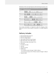
Delivery includes 1 EM 3732 COM-II twin receiver or 1 EM 3732-II twin receiver or 1 EM 3731-II single receiver 3 mains cables (with EU, UK and US plug) 2 BNC antenna daisy chain cables (50 Ω) 1 BNC word clock daisy chain cable (75 Ω) 4 device feet 1 RJ 45 Ethernet cable 2 antennas 1 instruction manual 1 CD ROM with: - the "Wireless Systems Manager" (WSM...
Delivery includes 1 EM 3732 COM-II twin receiver or 1 EM 3732-II twin receiver or 1 EM 3731-II single receiver 3 mains cables (with EU, UK and US plug) 2 BNC antenna daisy chain cables (50 Ω) 1 BNC word clock daisy chain cable (75 Ω) 4 device feet 1 RJ 45 Ethernet cable 2 antennas 1 instruction manual 1 CD ROM with: - the "Wireless Systems Manager" (WSM...
Instructions for use
Page 19
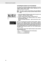
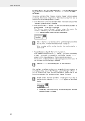
... when data is automatically muted. 18 The LED for signals and records the corresponding measured values. When selecting this receiver in the instruction manual of the "Wireless Systems Manager" manual. Putting the receiver into operation Scanning Connecting the receivers to the chapter "The 'RF Spectrum Analyzer' tool" of the "Wireless Systems Manager...
... when data is automatically muted. 18 The LED for signals and records the corresponding measured values. When selecting this receiver in the instruction manual of the "Wireless Systems Manager" manual. Putting the receiver into operation Scanning Connecting the receivers to the chapter "The 'RF Spectrum Analyzer' tool" of the "Wireless Systems Manager...
Instructions for use
Page 21
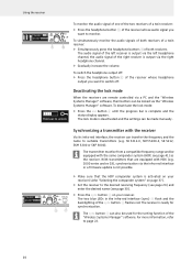
...Synchronizing a transmitter with HDX (e.g. 2000 series and es G3), synchronization via the right headphone channel. ̈ Gradually increase the volume. SK 5212-II, SKM 5200-II, SK 5212, SKM 5200 or SKP 3000). save want to page 22. 20 To switch the headphone output off . To deactivate the lock ...mode: ̈ Press the esc button 6 until the progress bar is not possible. The transmitter must be from a compatible frequency range and be made manually....
...Synchronizing a transmitter with HDX (e.g. 2000 series and es G3), synchronization via the right headphone channel. ̈ Gradually increase the volume. SK 5212-II, SKM 5200-II, SK 5212, SKM 5200 or SKP 3000). save want to page 22. 20 To switch the headphone output off . To deactivate the lock ...mode: ̈ Press the esc button 6 until the progress bar is not possible. The transmitter must be from a compatible frequency range and be made manually....
Instructions for use
Page 22
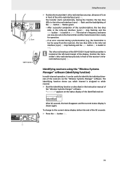
...transfer starts automatically. After successful completion of the 60 seconds: ̈ Press the esc button 6. 21 SKM 5200-II The infra-red interface of the SKM 5200-II hand-held transmitter is assigned to identify the individual channels of the receivers via the "Wireless Systems Manager" software....the receiver), the two blue LEDs in the infra-red interface (sync) A stop flashing and the sync button 9 is backlit in the instruction manual of the "Wireless Systems Manger" software. "Identified" appears on the transmitter and the transmission link is shown again. distance of 5 cm in ...
...transfer starts automatically. After successful completion of the 60 seconds: ̈ Press the esc button 6. 21 SKM 5200-II The infra-red interface of the SKM 5200-II hand-held transmitter is assigned to identify the individual channels of the receivers via the "Wireless Systems Manager" software....the receiver), the two blue LEDs in the infra-red interface (sync) A stop flashing and the sync button 9 is backlit in the instruction manual of the "Wireless Systems Manger" software. "Identified" appears on the transmitter and the transmission link is shown again. distance of 5 cm in ...
Instructions for use
Page 23
... For more information, please refer to page 20. The text "Sorted" automatically goes off after 1 second. For more information, refer to the instruction manual of the "Wireless Systems Manger" software. Each additional receiver whose sync button 9 you want to assign channel 1 for at least 1.5 seconds is deactivated....receivers at any time and to save this new channel assignment in a scene. ̈ Start the sorting function as described in the instruction manual of the "Wireless Systems Manger" software. ̈ Press and hold the sync button 9 of the receiver to which you press and ...
... For more information, please refer to page 20. The text "Sorted" automatically goes off after 1 second. For more information, refer to the instruction manual of the "Wireless Systems Manger" software. Each additional receiver whose sync button 9 you want to assign channel 1 for at least 1.5 seconds is deactivated....receivers at any time and to save this new channel assignment in a scene. ̈ Start the sorting function as described in the instruction manual of the "Wireless Systems Manger" software. ̈ Press and hold the sync button 9 of the receiver to which you press and ...
Instructions for use
Page 39
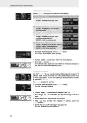
... next byte. ̈ Repeat the last two steps to enter all four bytes. ̈ After you can select the status display: Selectable status display 1. To manually assign an IP address: 192. 168. 192. 049. 0. 068. 0 Auto 78 DEV 777.005 M H z U.01 BANK CH HD P AF COM esc save ...0 to the setting mode of the operating menu. "Bank/Channel/Command" M displays the frequency bank, the channel H z number and the command display (EM 3732 COM-II receiver only) 03.03BANK HD P AF COM CH 776.000 NAME ̈ Change to the setting mode of the "Display" menu. 1 The current ...
... next byte. ̈ Repeat the last two steps to enter all four bytes. ̈ After you can select the status display: Selectable status display 1. To manually assign an IP address: 192. 168. 192. 049. 0. 068. 0 Auto 78 DEV 777.005 M H z U.01 BANK CH HD P AF COM esc save ...0 to the setting mode of the operating menu. "Bank/Channel/Command" M displays the frequency bank, the channel H z number and the command display (EM 3732 COM-II receiver only) 03.03BANK HD P AF COM CH 776.000 NAME ̈ Change to the setting mode of the "Display" menu. 1 The current ...

Instructions for use
Page 49
Sennheiser electronic GmbH & Co. KG Am Labor 1, 30900 Wedemark, Germany www.sennheiser.com Printed in Germany, Publ. 10/10, 542644/A01 Bedienungsanleitung Instruction manual Notice d'emploi Instrucciones de uso Istruzioni per l'uso Gebruiksaanwijzing
Sennheiser electronic GmbH & Co. KG Am Labor 1, 30900 Wedemark, Germany www.sennheiser.com Printed in Germany, Publ. 10/10, 542644/A01 Bedienungsanleitung Instruction manual Notice d'emploi Instrucciones de uso Istruzioni per l'uso Gebruiksaanwijzing