Brochure Wireless System Manager
Page 7
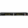
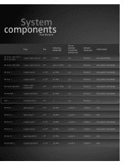
...; 19'' 36 MHz via Net 1 via Net 1 XLR yes Ethernet -/- System components Hardware Type Size EM 3731 / EM 3732 / EM 3732-COM single / dual receiver 19'' EM 2000 / EM 2050 single / dual receiver 19'' Switching bandwidth 90 MHz IR-sync between transmitter and receiver yes Network connection Audio output Ethernet XLR and AES-EBU up to 75 MHz yes Ethernet...
...; 19'' 36 MHz via Net 1 via Net 1 XLR yes Ethernet -/- System components Hardware Type Size EM 3731 / EM 3732 / EM 3732-COM single / dual receiver 19'' EM 2000 / EM 2050 single / dual receiver 19'' Switching bandwidth 90 MHz IR-sync between transmitter and receiver yes Network connection Audio output Ethernet XLR and AES-EBU up to 75 MHz yes Ethernet...
Instructions for use
Page 2
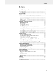
...of the EM 3731-II/EM 3732-II/EM 3732 COM-II receivers ...8 Overview of the displays 9 Reception display 10 Status display 11 Putting the receiver into operation 13 Fitting the device feet 13 Rack mounting 13 Connecting the antennas 14 Daisy chaining receivers 16 Connecting the receiver to the mains/disconnecting the receiver from ...menu 23 Working with the operating menu 24 Overview of the menus 25 Adjustment tips for the operating menu 29 Cleaning the receiver 40 Additional information 41 HiDyn plus™ (HDP) or HDX noise reduction 41 Squelch ...41 Diversity reception 42 If ...
...of the EM 3731-II/EM 3732-II/EM 3732 COM-II receivers ...8 Overview of the displays 9 Reception display 10 Status display 11 Putting the receiver into operation 13 Fitting the device feet 13 Rack mounting 13 Connecting the antennas 14 Daisy chaining receivers 16 Connecting the receiver to the mains/disconnecting the receiver from ...menu 23 Working with the operating menu 24 Overview of the menus 25 Adjustment tips for the operating menu 29 Cleaning the receiver 40 Additional information 41 HiDyn plus™ (HDP) or HDX noise reduction 41 Squelch ...41 Diversity reception 42 If ...
Instructions for use
Page 3
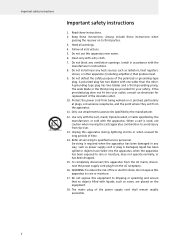
... into your safety. Protect the power cord from the AC receptacle. 16. Refer all servicing to third parties. 3. Always include these instructions when passing the receiver on to qualified service personnel. Do not use this apparatus to rain or moisture, does not operate normally, or has been dropped. 15. Do not...
... into your safety. Protect the power cord from the AC receptacle. 16. Refer all servicing to third parties. 3. Always include these instructions when passing the receiver on to qualified service personnel. Do not use this apparatus to rain or moisture, does not operate normally, or has been dropped. 15. Do not...
Instructions for use
Page 4
... allowed to the rear of a working day. Sennheiser, as the manufacturer, is therefore obliged to expressly point out possible health risks arising from use is used as this receiver. Important safety instructions Hazard warnings on the rear of the receiver The label shown on this label have the impression ... alert the user to high volumes This is opened. Danger of hearing damage due to the risk of electric shock if the receiver is a professional receiver. The following meaning: This symbol is attached to affect your hearing. The symbols on the left is intended to alert the ...
... allowed to the rear of a working day. Sennheiser, as the manufacturer, is therefore obliged to expressly point out possible health risks arising from use is used as this receiver. Important safety instructions Hazard warnings on the rear of the receiver The label shown on this label have the impression ... alert the user to high volumes This is opened. Danger of hearing damage due to the risk of electric shock if the receiver is a professional receiver. The following meaning: This symbol is attached to affect your hearing. The symbols on the left is intended to alert the ...

Instructions for use
Page 5
Important safety instructions Intended use of the EM 3731-II single receiver or the EM 3732-II and EM 3732 COM-II twin receivers includes: • having read these instructions, or under operating conditions which differ from those described herein. 4 "Improper use of the receiver Intended use " means using the receiver other than as described in these instructions, especially the chapter "Important safety instructions" on page 2, • using the receiver within the operating conditions and limitations described in this instruction manual.
Important safety instructions Intended use of the EM 3731-II single receiver or the EM 3732-II and EM 3732 COM-II twin receivers includes: • having read these instructions, or under operating conditions which differ from those described herein. 4 "Improper use of the receiver Intended use " means using the receiver other than as described in these instructions, especially the chapter "Important safety instructions" on page 2, • using the receiver within the operating conditions and limitations described in this instruction manual.
Instructions for use
Page 6
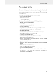
... • Infra-red synchronization of receiver settings with suitable transmitters • Both receivers of use. The product family is comprised of the following models: • EM 3732 COM-II twin receiver • EM 3732-II twin receiver • EM 3731-II single receiver All receivers of the product family have the ... daisy chaining up to a PC • Receivers can be monitored and remote controlled using the supplied Sennheiser WSM PC software • Operation via headphones 5 The product family The product family The receivers of the product family ensure highest reception reliability...
... • Infra-red synchronization of receiver settings with suitable transmitters • Both receivers of use. The product family is comprised of the following models: • EM 3732 COM-II twin receiver • EM 3732-II twin receiver • EM 3731-II single receiver All receivers of the product family have the ... daisy chaining up to a PC • Receivers can be monitored and remote controlled using the supplied Sennheiser WSM PC software • Operation via headphones 5 The product family The product family The receivers of the product family ensure highest reception reliability...
Instructions for use
Page 7
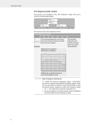
... 638 Range N 614 - 798 Range N-GB 606 - 790 Range P 776 - 960 400 600 800 1000 The receivers have seven frequency banks: Channel Frequency bank 1234 5 6 1 The receiving frequencies are factory- 2 preset (see enclosed frequency table) and cannot be subject to different channels within the... Risk of a multi-channel system to interference and intermodulation. The product family The frequency bank system The receivers are available in Low Intermodulation mode CAUTION! within the same frequency bank. 6 max. 60 Optimized for maximum transmission reliability U The...
... 638 Range N 614 - 798 Range N-GB 606 - 790 Range P 776 - 960 400 600 800 1000 The receivers have seven frequency banks: Channel Frequency bank 1234 5 6 1 The receiving frequencies are factory- 2 preset (see enclosed frequency table) and cannot be subject to different channels within the... Risk of a multi-channel system to interference and intermodulation. The product family The frequency bank system The receivers are available in Low Intermodulation mode CAUTION! within the same frequency bank. 6 max. 60 Optimized for maximum transmission reliability U The...
Instructions for use
Page 8
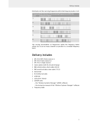
... varying accumulation of the "Wireless Systems Manager" software 1 Frequency table 7 the "Wireless Systems Manager" (WSM) software - Delivery includes 1 EM 3732 COM-II twin receiver or 1 EM 3732-II twin receiver or 1 EM 3731-II single receiver 3 mains cables (with EU, UK and US plug) 2 BNC antenna daisy chain cables (50 Ω) 1 BNC word clock daisy ...: - the instruction manual of frequencies within the frequency banks allows you to 6: Frequency Distribution of the receiving frequencies within the frequency banks 1 to use as many channels as possible in a crowded frequency band.
... varying accumulation of the "Wireless Systems Manager" software 1 Frequency table 7 the "Wireless Systems Manager" (WSM) software - Delivery includes 1 EM 3732 COM-II twin receiver or 1 EM 3732-II twin receiver or 1 EM 3731-II single receiver 3 mains cables (with EU, UK and US plug) 2 BNC antenna daisy chain cables (50 Ω) 1 BNC word clock daisy ...: - the instruction manual of frequencies within the frequency banks allows you to 6: Frequency Distribution of the receiving frequencies within the frequency banks 1 to use as many channels as possible in a crowded frequency band.
Instructions for use
Page 9
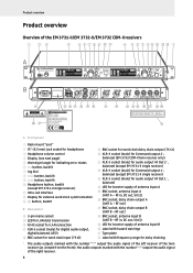
... Ω) S LED for booster supply of antenna input B T Label with hazard warnings U Type plate V Label with frequency range for booster supply of the EM 3731-II/EM 3732-II/EM 3732 COM-II receivers True Diversity Receiver EM 3732-II 776.000 A RF B % DEV M 300 PEAK H z 100 100 30 10 50 01.01BANK CH HD P AF COM μV 10 776.000 A RF B % DEV...
... Ω) S LED for booster supply of antenna input B T Label with hazard warnings U Type plate V Label with frequency range for booster supply of the EM 3731-II/EM 3732-II/EM 3732 COM-II receivers True Diversity Receiver EM 3732-II 776.000 A RF B % DEV M 300 PEAK H z 100 100 30 10 50 01.01BANK CH HD P AF COM μV 10 776.000 A RF B % DEV...
Instructions for use
Page 10
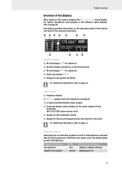
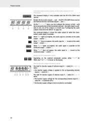
.... appears when the frequency is displayed º 6-step transmitter battery status display ¾ Command display (status display for the audio outputs AF and Command) (EM 3732 COM-II twin receiver only) µ Display for the compander system ¸ Display for dimming No operation Squelch not reached after 60 s 20 min Behavior of the different...
.... appears when the frequency is displayed º 6-step transmitter battery status display ¾ Command display (status display for the audio outputs AF and Command) (EM 3732 COM-II twin receiver only) µ Display for the compander system ¸ Display for dimming No operation Squelch not reached after 60 s 20 min Behavior of the different...
Instructions for use
Page 11
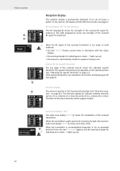
...goes off (see page 9). ´ · A RF B % DEV 300 PEAK 100 100 30 50 10 µV 10 Diversity display The receivers operate on the true diversity principle (see page 9). The squelch threshold can be adjusted via the operating menu (see "Adjusting the squelch threshold" on...period of time, the text "AF Peak" appears and the warning triangle for indicating error states 5 lights up red, • the receiver is excessively high, the receiver's audio level display "DEV" ¿ shows more than 100%. The diversity display · indicates whether diversity section A (i.e. When ...
...goes off (see page 9). ´ · A RF B % DEV 300 PEAK 100 100 30 50 10 µV 10 Diversity display The receivers operate on the true diversity principle (see page 9). The squelch threshold can be adjusted via the operating menu (see "Adjusting the squelch threshold" on...period of time, the text "AF Peak" appears and the warning triangle for indicating error states 5 lights up red, • the receiver is excessively high, the receiver's audio level display "DEV" ¿ shows more than 100%. The diversity display · indicates whether diversity section A (i.e. When ...
Instructions for use
Page 12
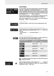
...). depending on the charge status of the transmitter's battery/accupack: Number of segments Charge status Accupack Battery approx. 100 % full approx. 80 % - With the EM 3732 COM-II receiver, the command display can also be changed in the operating menu, you can be displayed within the status display. In addition, the warning triangle for...
...). depending on the charge status of the transmitter's battery/accupack: Number of segments Charge status Accupack Battery approx. 100 % full approx. 80 % - With the EM 3732 COM-II receiver, the command display can also be changed in the operating menu, you can be displayed within the status display. In addition, the warning triangle for...
Instructions for use
Page 13
... J and/or L. COM When "COM" lights up when: • the booster supply voltage is applied to the corresponding antenna input A O and/or B R. with the EM 3732 COM-II twin receiver. When "COM" does not appear, the audio signal is avail- HD HD P X Display for the compander system Depending on the selected compander system, either...'s audio signal is available. The command display ¾ shows the audio output at the command output J and/or L. Besides the two audio outputs K and M the EM 3732 COM-II twin receiver also features the two command outputs J and L.
... J and/or L. COM When "COM" lights up when: • the booster supply voltage is applied to the corresponding antenna input A O and/or B R. with the EM 3732 COM-II twin receiver. When "COM" does not appear, the audio signal is avail- HD HD P X Display for the compander system Depending on the selected compander system, either...'s audio signal is available. The command display ¾ shows the audio output at the command output J and/or L. Besides the two audio outputs K and M the EM 3732 COM-II twin receiver also features the two command outputs J and L.
Instructions for use
Page 14
... by taking appropriate measures - especially when you are using an extension cable or a multi-outlet power strip. ̈ When installing the receiver in a closed or multi-rack assembly, please note that , during operation, the ambient temperature, the mechanical loading and the electrical potentials ...rack. ̈ The ambient temperature within the rack must not exceed the temperature limit specified in the specifications. ̈ When installing the receiver in a rack, take good care not to affect the ventilation required for safe operation or provide additional ventilation. ̈ Make sure ...
... by taking appropriate measures - especially when you are using an extension cable or a multi-outlet power strip. ̈ When installing the receiver in a closed or multi-rack assembly, please note that , during operation, the ambient temperature, the mechanical loading and the electrical potentials ...rack. ̈ The ambient temperature within the rack must not exceed the temperature limit specified in the specifications. ̈ When installing the receiver in a rack, take good care not to affect the ventilation required for safe operation or provide additional ventilation. ̈ Make sure ...
Instructions for use
Page 15
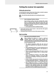
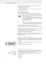
...! If uninsulated antennas come into contact with objects which conduct electricity. good reception conditions provided - To mount the receiver into a 19" rack: ̈ Slide the receiver into the 19" rack. ̈ Secure the rack mount "ears" 1 to BNC connector [), • 2 antenna holders Z, • 4 screws, ...large amount of installation work. ̈ Connect the antennas to the BNC sockets O and R at the rear of the receiver The supplied antennas can produce sparking and audio interference. ̈ Use insulated antennas. Connecting the antennas CAUTION! Danger of short-...
...! If uninsulated antennas come into contact with objects which conduct electricity. good reception conditions provided - To mount the receiver into a 19" rack: ̈ Slide the receiver into the 19" rack. ̈ Secure the rack mount "ears" 1 to BNC connector [), • 2 antenna holders Z, • 4 screws, ...large amount of installation work. ̈ Connect the antennas to the BNC sockets O and R at the rear of the receiver The supplied antennas can produce sparking and audio interference. ̈ Use insulated antennas. Connecting the antennas CAUTION! Danger of short-...
Instructions for use
Page 16
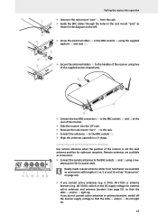
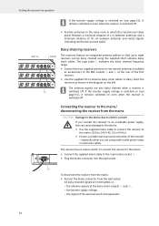
...the supplied screws respectively. [ -II \ NO P Q RS ̈ Connect the two BNC connectors [ to the BNC sockets O and R using the supplied washers Y and nuts X. Y ZX Z ̈ Secure the antenna holders Z to the handles of the receiver using two of the receiver is not the best antenna ...page 31) so that the LEDs N and/or S do not light up ; Ready-made coaxial antenna cables from Sennheiser are available as accessories with length of the receiver. ̈ Slide the receiver into operation 1 ̈ Unsecure the rack mount "ears" 1 from the rack. ̈ Guide the BNC cables ...
...the supplied screws respectively. [ -II \ NO P Q RS ̈ Connect the two BNC connectors [ to the BNC sockets O and R using the supplied washers Y and nuts X. Y ZX Z ̈ Secure the antenna holders Z to the handles of the receiver using two of the receiver is not the best antenna ...page 31) so that the LEDs N and/or S do not light up ; Ready-made coaxial antenna cables from Sennheiser are available as accessories with length of the receiver. ̈ Slide the receiver into operation 1 ̈ Unsecure the rack mount "ears" 1 from the rack. ̈ Guide the BNC cables ...
Instructions for use
Page 17
... daisy chained using multi-outlet power strips or extension cables. Damage to the device due to the mains/ disconnecting the receiver from the wall socket. To connect the receiver to the mains: ̈ Connect the supplied mains cable to 240 V AC, 50 or 60 Hz). ̈...left. the signal of 50 cm between antennas and metal objects (including reinforced concrete walls). the booster supply voltage, - The receiver has no mains switch. D To disconnect the receiver from the mains: ̈ Pull out the mains connector from the mains CAUTION! Maintain a minimum distance of 1 m between...
... daisy chained using multi-outlet power strips or extension cables. Damage to the device due to the mains/ disconnecting the receiver from the wall socket. To connect the receiver to the mains: ̈ Connect the supplied mains cable to 240 V AC, 50 or 60 Hz). ̈...left. the signal of 50 cm between antennas and metal objects (including reinforced concrete walls). the booster supply voltage, - The receiver has no mains switch. D To disconnect the receiver from the mains: ̈ Pull out the mains connector from the mains CAUTION! Maintain a minimum distance of 1 m between...
Instructions for use
Page 18
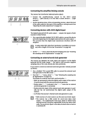
...-3M audio output G. lights up permanently when the digital audio output of the receiver is avail- flashes when "Ext." A ready-made AES3 cable from Sennheiser is used. • Both receivers of a twin receiver use the same word clock signal. • The receiver has a BNC socket for word clock daisy chain output I for external word clock...
...-3M audio output G. lights up permanently when the digital audio output of the receiver is avail- flashes when "Ext." A ready-made AES3 cable from Sennheiser is used. • Both receivers of a twin receiver use the same word clock signal. • The receiver has a BNC socket for word clock daisy chain output I for external word clock...
Instructions for use
Page 19
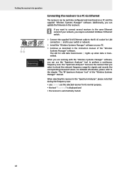
... RJ 45 Ethernet cable to the RJ 45 socket for its normal purpose, • the text "Scanning" is displayed and • the receiver is transmitted. When you are working with the "Wireless Systems Manager" software, you cannot use the "Spectrum Analyzer" tool to perform a continuous...your switch or network. ̈ Install the "Wireless Systems Manager" software on your PC. ̈ Continue as described in the receivers. When selecting this receiver in the "Spectrum Analyzer", please note that you can be centrally configured and monitored via a PC and the supplied "Wireless Systems Manager...
... RJ 45 Ethernet cable to the RJ 45 socket for its normal purpose, • the text "Scanning" is displayed and • the receiver is transmitted. When you are working with the "Wireless Systems Manager" software, you cannot use the "Spectrum Analyzer" tool to perform a continuous...your switch or network. ̈ Install the "Wireless Systems Manager" software on your PC. ̈ Continue as described in the receivers. When selecting this receiver in the "Spectrum Analyzer", please note that you can be centrally configured and monitored via a PC and the supplied "Wireless Systems Manager...

Instructions for use
Page 20
... switched off, - This common headphone socket 2 allows you to either monitor the audio signal of one of the two receivers of the EM 3732-II or EM 3732 COM-II, you only want to use one receiver or to simultaneously monitor the audio signals of the current firmware (behind "Software"). if the booster supply voltage is switched on...
... switched off, - This common headphone socket 2 allows you to either monitor the audio signal of one of the two receivers of the EM 3732-II or EM 3732 COM-II, you only want to use one receiver or to simultaneously monitor the audio signals of the current firmware (behind "Software"). if the booster supply voltage is switched on...
