Digital 9000 System Instruction for use
Page 2
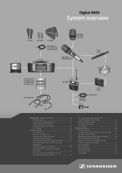
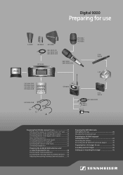
... receiver 11 EM 9046 CAB cable set 11 Antennas and antenna boosters 11 GZL 9000 antenna cables 11 SKM 9000/SKM 9000 COM radio microphone 12 Microphone heads for the SKM 9000 radio microphone 12 SK 9000 bodypack transmitter 12 Microphones for the SK 9000 bodypack transmitter 12 KA 9000 COM command adapter for the SK 9000 bodypack transmitter 12 CI 1-4 line...
... receiver 11 EM 9046 CAB cable set 11 Antennas and antenna boosters 11 GZL 9000 antenna cables 11 SKM 9000/SKM 9000 COM radio microphone 12 Microphone heads for the SKM 9000 radio microphone 12 SK 9000 bodypack transmitter 12 Microphones for the SK 9000 bodypack transmitter 12 KA 9000 COM command adapter for the SK 9000 bodypack transmitter 12 CI 1-4 line...

Digital 9000 System Instruction for use
Page 3
...78 Overview of the status displays 78 Overview of the menu items 79 Using the SK 9000 81 Switching the SK 9000 on /off 82 Activating/deactivating the automatic lock mode (Autolock 83 Basic functions of the Sennheiser operating menu 84 Overview of the status displays 84 Overview of the menu items 85... use 35 Changing the microphone head 37 Preparing the SK 9000 bodypack transmitter for use 37 Connecting the antenna 40 Connecting the KA 9000 COM command adapter 40 Preparing the L 60 charger for use 41 Cascading several chargers 41 Setting up or mounting the charger 41 Using the EM...
...78 Overview of the status displays 78 Overview of the menu items 79 Using the SK 9000 81 Switching the SK 9000 on /off 82 Activating/deactivating the automatic lock mode (Autolock 83 Basic functions of the Sennheiser operating menu 84 Overview of the status displays 84 Overview of the menu items 85... use 35 Changing the microphone head 37 Preparing the SK 9000 bodypack transmitter for use 37 Connecting the antenna 40 Connecting the KA 9000 COM command adapter 40 Preparing the L 60 charger for use 41 Cascading several chargers 41 Setting up or mounting the charger 41 Using the EM...
Digital 9000 System Instruction for use
Page 9
... receiver 11 EM 9046 CAB cable set 11 Antennas and antenna boosters 11 GZL 9000 antenna cables 11 SKM 9000/SKM 9000 COM radio microphone 12 Microphone heads for the SKM 9000 radio microphone 12 SK 9000 bodypack transmitter 12 Microphones for the SK 9000 bodypack transmitter 12 KA 9000 COM command adapter for the SK 9000 bodypack transmitter 12 CI 1-4 line...
... receiver 11 EM 9046 CAB cable set 11 Antennas and antenna boosters 11 GZL 9000 antenna cables 11 SKM 9000/SKM 9000 COM radio microphone 12 Microphone heads for the SKM 9000 radio microphone 12 SK 9000 bodypack transmitter 12 Microphones for the SK 9000 bodypack transmitter 12 KA 9000 COM command adapter for the SK 9000 bodypack transmitter 12 CI 1-4 line...
Digital 9000 System Instruction for use
Page 12
... - up your Sennheiser service partner. EM 9046 CAB cable set 2 RF patch cable (type N, 50 ) 1 Ethernet patch cable (RJ45 connectors, CAT 5) 1 Word clock patch cable (BNC, 75 ) Antennas and antenna boosters 1 A 9000 omni-directional antenna or 1 AD 9000 directional antenna or 1 AB 9000 antenna booster 1 supplement GZL 9000 antenna cables 1 GZL 9000-A5 antenna cable...
... - up your Sennheiser service partner. EM 9046 CAB cable set 2 RF patch cable (type N, 50 ) 1 Ethernet patch cable (RJ45 connectors, CAT 5) 1 Word clock patch cable (BNC, 75 ) Antennas and antenna boosters 1 A 9000 omni-directional antenna or 1 AD 9000 directional antenna or 1 AB 9000 antenna booster 1 supplement GZL 9000 antenna cables 1 GZL 9000-A5 antenna cable...
Digital 9000 System Instruction for use
Page 17
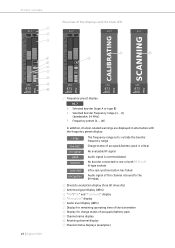
no signal peak booster sync fail encryption The frequency range set is outside the booster frequency range Charge status of accupack/battery pack is critical No evaluable RF signal Audio signal is overmodulated No booster connected ...-related warnings are displayed in alternation with the frequency preset display: range low bat. Product overview 1 A1.7 2 3 4 fs HD 5 6 3:10 7 8 CH3 9 473 0 800 16 | Digital 9000 Overview of accupack/battery pack 9 Channel name display 0 Receiving channel display A Channel status displays (examples)
no signal peak booster sync fail encryption The frequency range set is outside the booster frequency range Charge status of accupack/battery pack is critical No evaluable RF signal Audio signal is overmodulated No booster connected ...-related warnings are displayed in alternation with the frequency preset display: range low bat. Product overview 1 A1.7 2 3 4 fs HD 5 6 3:10 7 8 CH3 9 473 0 800 16 | Digital 9000 Overview of accupack/battery pack 9 Channel name display 0 Receiving channel display A Channel status displays (examples)
Digital 9000 System Instruction for use
Page 18
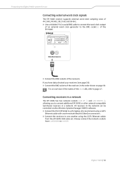
The EM 9046 receiver generates its own word clock signal. The "Word clock" menu item is set to the last set or active word clock rate. As soon as an external word clock signal is present at the WORD CLOCK IN BNC socket 9, the digital audio ... it and the clock LED 6 lights up constantly. The word clock rate of the EM 9046 automatically synchronizes with an external word clock signal. Digital 9000 | 17
The EM 9046 receiver generates its own word clock signal. The "Word clock" menu item is set to the last set or active word clock rate. As soon as an external word clock signal is present at the WORD CLOCK IN BNC socket 9, the digital audio ... it and the clock LED 6 lights up constantly. The word clock rate of the EM 9046 automatically synchronizes with an external word clock signal. Digital 9000 | 17
Digital 9000 System Instruction for use
Page 19
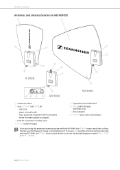
...B1" ... Product overview Antennas and antenna boosters A/AB/AD9000 1 1 5 2 2 5 3 4 A 9000 6 2 5 4 3 RF out Filter Com on 49 8 7 4 AB 9000 AD 9000 1 Antenna surface 2 and 9: "Com" and "On" LED - "B8"). 18 | Digital 9000 red: error - white: firmware update in progress 3 Hole for connection of safety wires 4 RF out socket... (N-type) 5 Type plate (not visible here) 6 RF in socket (N-type) (AB 9000 only) 7 Stand adapter 8 "Filter" rotary switch (see below) If you to set . green: manual mode - blue: automatic mode (EM 9046-controlled) - If you are using the ...
...B1" ... Product overview Antennas and antenna boosters A/AB/AD9000 1 1 5 2 2 5 3 4 A 9000 6 2 5 4 3 RF out Filter Com on 49 8 7 4 AB 9000 AD 9000 1 Antenna surface 2 and 9: "Com" and "On" LED - "B8"). 18 | Digital 9000 red: error - white: firmware update in progress 3 Hole for connection of safety wires 4 RF out socket... (N-type) 5 Type plate (not visible here) 6 RF in socket (N-type) (AB 9000 only) 7 Stand adapter 8 "Filter" rotary switch (see below) If you to set . green: manual mode - blue: automatic mode (EM 9046-controlled) - If you are using the ...
Digital 9000 System Instruction for use
Page 20
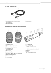
...5 m, 10 m and 20 m 2 N-type connector 3 N-type socket SKM 9000/SKM 9000 COM radio microphone 1 2 4 56 8 90 A BC 7D 3 D 1 Microphone head 2 Contacts of microphone head 3 Contacts of radio microphone 9 DOWN button 0 UP button A SET button B ON/OFF button with ESC function (cancel) - lights up constantly: ...radio microphone is operational C Antenna D Catches for 2 AA size cells 8 Body of radio microphone 4 COMMAND button (SKM 9000 COM) 5 Display panel 6 Infra-red ...
...5 m, 10 m and 20 m 2 N-type connector 3 N-type socket SKM 9000/SKM 9000 COM radio microphone 1 2 4 56 8 90 A BC 7D 3 D 1 Microphone head 2 Contacts of microphone head 3 Contacts of radio microphone 9 DOWN button 0 UP button A SET button B ON/OFF button with ESC function (cancel) - lights up constantly: ...radio microphone is operational C Antenna D Catches for 2 AA size cells 8 Body of radio microphone 4 COMMAND button (SKM 9000 COM) 5 Display panel 6 Infra-red ...

Digital 9000 System Instruction for use
Page 22
lights up constantly: transmitter is less than 30 minutes - Product overview SK 9000 bodypack transmitter 1 2 34 5 C 9 6 7 0 8 B 9 0 D A E F 1 3-pin special audio socket 7 SET button for accupack/battery pack - CI 1-4 Sennheiser instrument cable for 8 UP button - KA 9000 COM command adapter 0 Snap-in elements 2 ON/OFF button for accupack/battery pack with high levels: audio signal is excessively high...
lights up constantly: transmitter is less than 30 minutes - Product overview SK 9000 bodypack transmitter 1 2 34 5 C 9 6 7 0 8 B 9 0 D A E F 1 3-pin special audio socket 7 SET button for accupack/battery pack - CI 1-4 Sennheiser instrument cable for 8 UP button - KA 9000 COM command adapter 0 Snap-in elements 2 ON/OFF button for accupack/battery pack with high levels: audio signal is excessively high...
Digital 9000 System Instruction for use
Page 27
... EM 9046 AAO EM 9046 DAO EM 9046 CAB EM 9046 CAB SK 9000 B 61 BA 61 KA 9000 COM MKE 1 MKE 2 ... EM 9046 SKM 9000 SKM 9000 COM Preparing the Digital 9000 system for use 41 Cascading several chargers 41 Setting up or mounting the charger 41 CI 1-4 Preparing the EM 9046 ... the SKM 9000 radio microphone for use 35 Changing the microphone head 37 Preparing the SK 9000 bodypack transmitter for use 37 Connecting the antenna 40 Connecting the KA 9000 COM command adapter 40 Preparing the L 60 charger for use WSM A 9000 AB 9000 AD 9000 GZL 9000-A5 GZL 9000-A10 GZL 9000-A20 ME 9002...
... EM 9046 AAO EM 9046 DAO EM 9046 CAB EM 9046 CAB SK 9000 B 61 BA 61 KA 9000 COM MKE 1 MKE 2 ... EM 9046 SKM 9000 SKM 9000 COM Preparing the Digital 9000 system for use 41 Cascading several chargers 41 Setting up or mounting the charger 41 CI 1-4 Preparing the EM 9046 ... the SKM 9000 radio microphone for use 35 Changing the microphone head 37 Preparing the SK 9000 bodypack transmitter for use 37 Connecting the antenna 40 Connecting the KA 9000 COM command adapter 40 Preparing the L 60 charger for use WSM A 9000 AB 9000 AD 9000 GZL 9000-A5 GZL 9000-A10 GZL 9000-A20 ME 9002...
Digital 9000 System Instruction for use
Page 28
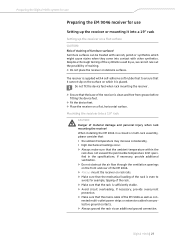
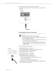
...rack mounting the receiver! If necessary, provide overcurrent protection. ̈ Make sure that it cannot slip on the surface on delicate surfaces. Digital 9000 | 27 When installing the EM 9046 in a closed or multi-rack assembly, please consider that • the ambient temperature may increase considerably...Place the receiver on a flat, horizontal surface. Mounting the receiver into contact with 4 self-adhesive soft rubber feet to avoid, for use Setting up the receiver on a flat surface CAUTION! The receiver is supplied with other synthetics. Risk of staining of the EM 9046 as well...
...rack mounting the receiver! If necessary, provide overcurrent protection. ̈ Make sure that it cannot slip on the surface on delicate surfaces. Digital 9000 | 27 When installing the EM 9046 in a closed or multi-rack assembly, please consider that • the ambient temperature may increase considerably...Place the receiver on a flat, horizontal surface. Mounting the receiver into contact with 4 self-adhesive soft rubber feet to avoid, for use Setting up the receiver on a flat surface CAUTION! The receiver is supplied with other synthetics. Risk of staining of the EM 9046 as well...
Digital 9000 System Instruction for use
Page 31
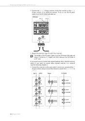
...LAN DOWN LAN UP LAN DOWN EM9046 ANT A ANT B RF OUT B RF OUT A 30 | Digital 9000 ̈ Repeat the previous steps for use the RF patch cables from LAN DOWN to the RF IN N-type... sockets of the RF patch cables from the EM 9046 CAB cable set . The length of an additional receiver. If you want to pass on word clock signals between ...type sockets. Always connect the network sockets from the EM 9046 CAB cable set allows a distance of the first receiver to LAN UP. Preparing the Digital 9000 system for up to connect daisy chained receivers in a network (see ...
...LAN DOWN LAN UP LAN DOWN EM9046 ANT A ANT B RF OUT B RF OUT A 30 | Digital 9000 ̈ Repeat the previous steps for use the RF patch cables from LAN DOWN to the RF IN N-type... sockets of the RF patch cables from the EM 9046 CAB cable set . The length of an additional receiver. If you want to pass on word clock signals between ...type sockets. Always connect the network sockets from the EM 9046 CAB cable set allows a distance of the first receiver to LAN UP. Preparing the Digital 9000 system for up to connect daisy chained receivers in a network (see ...
Digital 9000 System Instruction for use
Page 32
... of the receivers in a network. We recommend using a CAT5 Ethernet cable with crush-resistant Neutrik EtherCon connectors. ̈ Connect the receivers to LAN UP. Digital 9000 | 31 EM9046 A B C D E F 9 BNC (Word Clock in the network can be controlled via the Wireless Systems Manager (WSM) software. ̈ Connect the first.... Always connect the network sockets from LAN DOWN to one another using the CAT5 Ethernet cables from the EM 9046 CAB cable set. If you to connect additional EM 9046 or other network-compatible Sennheiser receivers in the order shown on page 30.
... of the receivers in a network. We recommend using a CAT5 Ethernet cable with crush-resistant Neutrik EtherCon connectors. ̈ Connect the receivers to LAN UP. Digital 9000 | 31 EM9046 A B C D E F 9 BNC (Word Clock in the network can be controlled via the Wireless Systems Manager (WSM) software. ̈ Connect the first.... Always connect the network sockets from LAN DOWN to one another using the CAT5 Ethernet cables from the EM 9046 CAB cable set. If you to connect additional EM 9046 or other network-compatible Sennheiser receivers in the order shown on page 30.
Digital 9000 System Instruction for use
Page 33
...50 or 60 Hz). ̈ Ensure a reliable mains ground connection of the receiver - To disconnect the receiver from the mains. 32 | Digital 9000 Preparing the Digital 9000 system for use If you are interrupted, i.e.: - the antenna signals at the daisy chain outputs G and H, - the booster supply voltage, -... to position "0". All daisy chained signals are using multi-outlet power strips or extension cables. To connect the receiver to the mains: ̈ Set the ON/OFF switch 1 to position "0". ̈ Connect the supplied mains cable to the 3-pin mains socket 2. ̈ Plug the mains ...
...50 or 60 Hz). ̈ Ensure a reliable mains ground connection of the receiver - To disconnect the receiver from the mains. 32 | Digital 9000 Preparing the Digital 9000 system for use If you are interrupted, i.e.: - the antenna signals at the daisy chain outputs G and H, - the booster supply voltage, -... to position "0". All daisy chained signals are using multi-outlet power strips or extension cables. To connect the receiver to the mains: ̈ Set the ON/OFF switch 1 to position "0". ̈ Connect the supplied mains cable to the 3-pin mains socket 2. ̈ Plug the mains ...
Digital 9000 System Instruction for use
Page 36
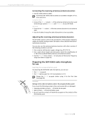
... you can use Connecting the receiving antennas/antenna boosters ̈ Use GZL 9000 antenna cables. Sennheiser GZL 9000 antenna cables are met: ̈ Use a receiver with booster supply voltage (e.g. No further settings need to be made on page 34). Preparing the SKM 9000 radio microphone for the first time (see table on the A/AB/AD...
... you can use Connecting the receiving antennas/antenna boosters ̈ Use GZL 9000 antenna cables. Sennheiser GZL 9000 antenna cables are met: ̈ Use a receiver with booster supply voltage (e.g. No further settings need to be made on page 34). Preparing the SKM 9000 radio microphone for the first time (see table on the A/AB/AD...
Digital 9000 System Instruction for use
Page 37
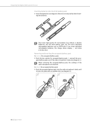
... the batteries (see diagram). Do not insert individual rechargeable batteries such as NiMH cells. When removing the accupack/battery pack, the settings of the radio microphone's body (see diagram 2). 1 2 36 | Digital 9000 If you insert individual rechargeable batteries, the charge status display 1 will show a wrong value. pack/battery pack out of the.../battery pack To remove the accupack/battery pack: ̈ Push the two catches for use Inserting batteries into the B 60 battery pack. Preparing the Digital 9000 system for accupack/battery pack D and pull the accu-
... the batteries (see diagram). Do not insert individual rechargeable batteries such as NiMH cells. When removing the accupack/battery pack, the settings of the radio microphone's body (see diagram 2). 1 2 36 | Digital 9000 If you insert individual rechargeable batteries, the charge status display 1 will show a wrong value. pack/battery pack out of the.../battery pack To remove the accupack/battery pack: ̈ Push the two catches for use Inserting batteries into the B 60 battery pack. Preparing the Digital 9000 system for accupack/battery pack D and pull the accu-
Digital 9000 System Instruction for use
Page 42
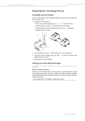
...polish or synthetics which might cause stains when they come into contact with other chargers. Digital 9000 | 41 Tighten the two screws 6. 7 6 5 ̈ Unscrew the two screws 7 at the bottom of surfaces! Setting up or mounting the charger CAUTION! Risk of staining of one charger. - Despite a ...thorough testing of the materials used by the NT 3-1 mains unit. ̈ Prepare the L 60 chargers: - Preparing the Digital 9000 system for use Preparing the L 60 ...
...polish or synthetics which might cause stains when they come into contact with other chargers. Digital 9000 | 41 Tighten the two screws 6. 7 6 5 ̈ Unscrew the two screws 7 at the bottom of surfaces! Setting up or mounting the charger CAUTION! Risk of staining of one charger. - Despite a ...thorough testing of the materials used by the NT 3-1 mains unit. ̈ Prepare the L 60 chargers: - Preparing the Digital 9000 system for use Preparing the L 60 ...
Digital 9000 System Instruction for use
Page 45
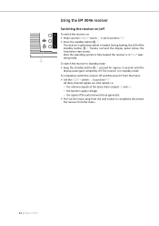
... seconds until the display panel goes completely off and disconnect it from the mains. 44 | Digital 9000 Using the EM 9046 receiver Switching the receiver on/off To switch the receiver on: ̈ ... mode. the signal of the standby button 3 flashes red and the display panel shows the Sennheiser start screen. During loading, the LED of the external word clock generator. ̈ Pull out... the mains plug from the wall socket to completely disconnect the receiver from the mains: ̈ Set the ON/OFF switch 1 to position "1". ̈ Press the standby button 3. the antenna signals at...
... seconds until the display panel goes completely off and disconnect it from the mains. 44 | Digital 9000 Using the EM 9046 receiver Switching the receiver on/off To switch the receiver on: ̈ ... mode. the signal of the standby button 3 flashes red and the display panel shows the Sennheiser start screen. During loading, the LED of the external word clock generator. ̈ Pull out... the mains plug from the wall socket to completely disconnect the receiver from the mains: ̈ Set the ON/OFF switch 1 to position "1". ̈ Press the standby button 3. the antenna signals at...
Digital 9000 System Instruction for use
Page 46
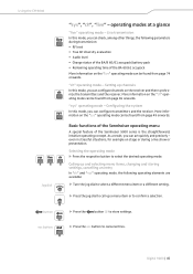
..." operating mode, the following parameters during a live " operating mode - Selecting the operating mode ̈ Press the respective button to store settings. Digital 9000 | 45 Configuring the system sys In this mode, you can be found from page 65 onwards. button ̈ Press the button F ... the BA/B 60/61 accupack/battery pack • Remaining operating time of the Sennheiser 9000 series is the straightforward, intuitive operating concept. sys live ch Jog dial Basic functions of the Sennheiser operating menu A special feature of the BA 60/61 accupack More information on the...
..." operating mode, the following parameters during a live " operating mode - Selecting the operating mode ̈ Press the respective button to store settings. Digital 9000 | 45 Configuring the system sys In this mode, you can be found from page 65 onwards. button ̈ Press the button F ... the BA/B 60/61 accupack/battery pack • Remaining operating time of the Sennheiser 9000 series is the straightforward, intuitive operating concept. sys live ch Jog dial Basic functions of the Sennheiser operating menu A special feature of the BA 60/61 accupack More information on the...
Digital 9000 System Instruction for use
Page 48
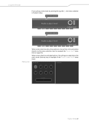
... called up a menu item by way of example of the "Audio output level" menu item): EM 9046 AAO 1 2 3 4 0 0 0 0 EM 9046 DAO 5 6 7 8 0 0 0 0 Analog multicore 00 0 Digital 9000 | 47 When a menu item has extended options, the settings are adjusted on page 55).
... called up a menu item by way of example of the "Audio output level" menu item): EM 9046 AAO 1 2 3 4 0 0 0 0 EM 9046 DAO 5 6 7 8 0 0 0 0 Analog multicore 00 0 Digital 9000 | 47 When a menu item has extended options, the settings are adjusted on page 55).