

User Manual
Page 7
...the batteries 13 Using the remote control unit 13 Cautions regarding remote control unit ... 13 Part names 14 Display 14 AVC System 15 Remote control unit 16 Watching TV 17 Antennas 17 Cable converter/VCR connection 17 Outdoor antenna connection 19 ... Moving the picture on the screen 48 Auto Sync. adjustment (PC input mode only) ... 49 Fine Sync. Contents IMPORTANT INFORMATION 1 DEAR SHARP CUSTOMER 3 IMPORTANT SAFETY PRECAUTIONS 3 Contents 6 Supplied accessories 7 Preparation 8 Attaching the speakers 8 Where to control other devices 70 Appendix 76 Troubleshooting...
...the batteries 13 Using the remote control unit 13 Cautions regarding remote control unit ... 13 Part names 14 Display 14 AVC System 15 Remote control unit 16 Watching TV 17 Antennas 17 Cable converter/VCR connection 17 Outdoor antenna connection 19 ... Moving the picture on the screen 48 Auto Sync. adjustment (PC input mode only) ... 49 Fine Sync. Contents IMPORTANT INFORMATION 1 DEAR SHARP CUSTOMER 3 IMPORTANT SAFETY PRECAUTIONS 3 Contents 6 Supplied accessories 7 Preparation 8 Attaching the speakers 8 Where to control other devices 70 Appendix 76 Troubleshooting...

User Manual
Page 8
...8226; AC cords enclosed in this product are for AVC System) QACCD3097CEPZ Page 10 NOTE • Always use the AC cord supplied with the Liquid Crystal Television and the one supplied with the product. SHARP ELECTRONICS CORPORATION 1300 Naperville Drive, Romeoville, Illinois 60446-1091...-A059WJSA PSPAHA101WJZZ GLEGGA013WJZZ XBPSN40P14JS0 Stand (g1) Stand cushion (g4) Stand spacer (g4) Stand screw (g2) Page 12 Operation manual (g1) LC-37HV4U TINS-A529WJZZ RSP-ZA027WJN1 (Left) RSP-ZA027WJN2 (Right) QCNW-6117CEZZ Page 10 AC cord (g2) XBBSF40P25000 (for Display) QACCDA019WJPZ Speaker (Lg1...
...8226; AC cords enclosed in this product are for AVC System) QACCD3097CEPZ Page 10 NOTE • Always use the AC cord supplied with the Liquid Crystal Television and the one supplied with the product. SHARP ELECTRONICS CORPORATION 1300 Naperville Drive, Romeoville, Illinois 60446-1091...-A059WJSA PSPAHA101WJZZ GLEGGA013WJZZ XBPSN40P14JS0 Stand (g1) Stand cushion (g4) Stand spacer (g4) Stand screw (g2) Page 12 Operation manual (g1) LC-37HV4U TINS-A529WJZZ RSP-ZA027WJN1 (Left) RSP-ZA027WJN2 (Right) QCNW-6117CEZZ Page 10 AC cord (g2) XBBSF40P25000 (for Display) QACCDA019WJPZ Speaker (Lg1...
User Manual
Page 10
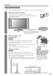
.... • Do not remove the stand from the Display unless using an optional bracket to place the System "System" means the Display and AVC System. Handling the AVC System CAUTION • Do not put your other hand. CAUTION Adjust the screen with one hand on the Display speakers. • Keep enough..., but never on the Display and tilt the screen while steadying the stand with no direct sunlight and good ventilation. • The Display and the AVC System are connected by the system cable. (See page 10 for details.) Display System cable If you want to place the System. 1 Selecting the...
.... • Do not remove the stand from the Display unless using an optional bracket to place the System "System" means the Display and AVC System. Handling the AVC System CAUTION • Do not put your other hand. CAUTION Adjust the screen with one hand on the Display speakers. • Keep enough..., but never on the Display and tilt the screen while steadying the stand with no direct sunlight and good ventilation. • The Display and the AVC System are connected by the system cable. (See page 10 for details.) Display System cable If you want to place the System. 1 Selecting the...

User Manual
Page 11
... (WHITE) Connect the plug into the terminal and secure it by tightening the thumb screws. Preparation Setting the System After putting the Display and the AVC System in place, connect the system cables and AC cords. Press down the two upper hooks to remove the cover toward you . 2 Connecting the system... cable and the AC cord to the AVC System System cable AVC System (rear view) (GRAY) (WHITE) AC cord CAUTION • TO PREVENT RISK OF ELECTRIC SHOCK, DO NOT TOUCH UN-INSULATED PARTS OF ANY...
... (WHITE) Connect the plug into the terminal and secure it by tightening the thumb screws. Preparation Setting the System After putting the Display and the AVC System in place, connect the system cables and AC cords. Press down the two upper hooks to remove the cover toward you . 2 Connecting the system... cable and the AC cord to the AVC System System cable AVC System (rear view) (GRAY) (WHITE) AC cord CAUTION • TO PREVENT RISK OF ELECTRIC SHOCK, DO NOT TOUCH UN-INSULATED PARTS OF ANY...

User Manual
Page 13
...Small hole Big hole Thick bulge 4 Attach the stand using the stand unit. • Use the supplied stand unit for installing the AVC System vertically in an upright position. 1 Stick each cushion to the stand as this can ask a qualified service personnel about using an... (See the bracket instructions for improper mounting or mounting that come with the stand How to install the AVC System vertically using the stand screws as shown. SHARP bears no responsibility for details.) Vertical mounting Angular mounting CAUTION • Installing the Liquid Crystal Television requires special...
...Small hole Big hole Thick bulge 4 Attach the stand using the stand unit. • Use the supplied stand unit for installing the AVC System vertically in an upright position. 1 Stick each cushion to the stand as this can ask a qualified service personnel about using an... (See the bracket instructions for improper mounting or mounting that come with the stand How to install the AVC System vertically using the stand screws as shown. SHARP bears no responsibility for details.) Vertical mounting Angular mounting CAUTION • Installing the Liquid Crystal Television requires special...

User Manual
Page 16
... (AUDIO L/R) INPUT 2 terminal (VIDEO) INPUT 2 terminal (S-VIDEO) MONITOR OUTPUT terminal (S-VIDEO) MONITOR OUTPUT terminal (VIDEO) MONITOR OUTPUT terminals (AUDIO L/R) 15 Part names AVC System Headphone PC INPUT terminal (AUDIO) (When connecting headphones, the sound from the Front view PC INPUT terminal (ANALOG RGB) speakers is muted.) STANDBY/ON... CLEAR* MAIN POWER button INPUT 4 terminals (AUDIO L/R) INPUT 4 terminal (VIDEO) INPUT 4 terminal (S-VIDEO) How to open the door. * If the AVC System is in the diagram, lightly with the end of a ballpoint pen or other pointed object.
... (AUDIO L/R) INPUT 2 terminal (VIDEO) INPUT 2 terminal (S-VIDEO) MONITOR OUTPUT terminal (S-VIDEO) MONITOR OUTPUT terminal (VIDEO) MONITOR OUTPUT terminals (AUDIO L/R) 15 Part names AVC System Headphone PC INPUT terminal (AUDIO) (When connecting headphones, the sound from the Front view PC INPUT terminal (ANALOG RGB) speakers is muted.) STANDBY/ON... CLEAR* MAIN POWER button INPUT 4 terminals (AUDIO L/R) INPUT 4 terminal (VIDEO) INPUT 4 terminal (S-VIDEO) How to open the door. * If the AVC System is in the diagram, lightly with the end of a ballpoint pen or other pointed object.
User Manual
Page 18
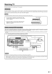
A 75-ohm system is made with F-type connector that can easily be connected at the rear of the AVC System. Signal reception may fail if improperly connected. • Be sure to remember what kind of connection is made with your System. • Shown here ...
A 75-ohm system is made with F-type connector that can easily be connected at the rear of the AVC System. Signal reception may fail if improperly connected. • Be sure to remember what kind of connection is made with your System. • Shown here ...

User Manual
Page 21
Display (rear view) AVC System (rear view) AC cord AC cord NOTE • Always turn off the main power of the Display and AVC System when connecting the AC cords. • Disconnect the AC cords from the AC outlet, Display and AVC System when the System is not going to be used for a long period of time. 20 Watching TV Connecting the AC cord Connect the AC cords after all component connections have been completed.
Display (rear view) AVC System (rear view) AC cord AC cord NOTE • Always turn off the main power of the Display and AVC System when connecting the AC cords. • Disconnect the AC cords from the AC outlet, Display and AVC System when the System is not going to be used for a long period of time. 20 Watching TV Connecting the AC cord Connect the AC cords after all component connections have been completed.

User Manual
Page 22
...on the Display. • The System enters standby mode and the image on the screen disappears. • Both the STANDBY/ON indicator on the AVC System and the POWER indicator on the Display change from the AC outlet. Red The System is in standby mode. Green The System is unplugged...POWER indicator on the Display flashes red. 3 Press MAIN POWER on the Display. • The POWER indicator on . First time turning on the AVC System AVC System MAIN STANDBY/ON indicator POWER TV POWER TV CBL VCR DVD /SAT /LD /DTV ANT-A/B INPUT AV FRONT MODE SURROUND MTS CC VIEW MODE...
...on the Display. • The System enters standby mode and the image on the screen disappears. • Both the STANDBY/ON indicator on the AVC System and the POWER indicator on the Display change from the AC outlet. Red The System is in standby mode. Green The System is unplugged...POWER indicator on the Display flashes red. 3 Press MAIN POWER on the Display. • The POWER indicator on . First time turning on the AVC System AVC System MAIN STANDBY/ON indicator POWER TV POWER TV CBL VCR DVD /SAT /LD /DTV ANT-A/B INPUT AV FRONT MODE SURROUND MTS CC VIEW MODE...

User Manual
Page 23
Example CH Search ANT-A Air [ 2] 2 Press c/d to select "Air" or "Cable" for ANT- A, then press a/b to 19.) 3. Connect the antenna cable to the AVC System. (See pages 17 to move down. Plug in the AC cord to select "Air" or "Cable" for ANT- Press c/d to the AC outlet. (See ...
Example CH Search ANT-A Air [ 2] 2 Press c/d to select "Air" or "Cable" for ANT- A, then press a/b to 19.) 3. Connect the antenna cable to the AVC System. (See pages 17 to move down. Plug in the AC cord to select "Air" or "Cable" for ANT- Press c/d to the AC outlet. (See ...

User Manual
Page 40
NOTE • "Disable" is factory preset value. 39 NOTE • "Disable" is factory preset value. • When a TV program finishes, and the AVC System receives signal input, this function may not operate. • Five minutes before the power shuts down, remaining time displays every minute. No operation off ...
NOTE • "Disable" is factory preset value. 39 NOTE • "Disable" is factory preset value. • When a TV program finishes, and the AVC System receives signal input, this function may not operate. • Five minutes before the power shuts down, remaining time displays every minute. No operation off ...

User Manual
Page 42
... on the Display. DVD player Digital TV tuner S-VIDEO S-VIDEO AV Y/PB/PR Y/PB/PR AV DVI AVC System (rear view) S-VIDEO AV VCR AV S-VIDEO AV Receiver (Built-in Tuner Amp) AVC System (front view) PC PC-AUDIO ANALOG RGB AV S-VIDEO Game console/ Camcorder CAUTION • To protect... all equipment, always turn off the AVC System before making connections. 41 Using external equipment You can connect many types of external equipment to a DVD player, VCR, Digital TV tuner, PC,...
... on the Display. DVD player Digital TV tuner S-VIDEO S-VIDEO AV Y/PB/PR Y/PB/PR AV DVI AVC System (rear view) S-VIDEO AV VCR AV S-VIDEO AV Receiver (Built-in Tuner Amp) AVC System (front view) PC PC-AUDIO ANALOG RGB AV S-VIDEO Game console/ Camcorder CAUTION • To protect... all equipment, always turn off the AVC System before making connections. 41 Using external equipment You can connect many types of external equipment to a DVD player, VCR, Digital TV tuner, PC,...

User Manual
Page 43
...; Each time INPUT is stored and can use the INPUT 1 terminal when connecting to change the input signal type setting on the "INPUT SOURCE" menu. AVC System (rear view) Component video cable (commercially available) When using INPUT on the remote control unit or on the Display. (See page 50.) Then select...
...; Each time INPUT is stored and can use the INPUT 1 terminal when connecting to change the input signal type setting on the "INPUT SOURCE" menu. AVC System (rear view) Component video cable (commercially available) When using INPUT on the remote control unit or on the Display. (See page 50.) Then select...

User Manual
Page 44
AVC System (rear view) TV POWER TV CBL VCR DVD /SAT /LD /DTV ANT-A/B INPUT AV FRONT MODE SURROUND MTS CC VIEW MODE TWIN PICTURE FREEZE ...
AVC System (rear view) TV POWER TV CBL VCR DVD /SAT /LD /DTV ANT-A/B INPUT AV FRONT MODE SURROUND MTS CC VIEW MODE TWIN PICTURE FREEZE ...

User Manual
Page 45
... page 50.) The setting is compatible with 1080I, 720P, 480P and VGA (60Hz). • Use the PC INPUT terminals on the front of the AVC System when connecting a PC. (See page 46.) • When connecting to the DVI-DIGITAL INPUT terminal, be selected on the "INPUT SOURCE" menu...TV tuner Connecting a Digital TV tuner You can be sure to use the INPUT 3 terminal when connecting a Digital TV tuner and other audiovisual equipment. AVC System (rear view) Component video cable (commercially available) When using component video cable, select "COMPONENT" for "Input Select" in the menu. Input ...
... page 50.) The setting is compatible with 1080I, 720P, 480P and VGA (60Hz). • Use the PC INPUT terminals on the front of the AVC System when connecting a PC. (See page 46.) • When connecting to the DVI-DIGITAL INPUT terminal, be selected on the "INPUT SOURCE" menu...TV tuner Connecting a Digital TV tuner You can be sure to use the INPUT 3 terminal when connecting a Digital TV tuner and other audiovisual equipment. AVC System (rear view) Component video cable (commercially available) When using component video cable, select "COMPONENT" for "Input Select" in the menu. Input ...

User Manual
Page 46
NOTE • Each time INPUT is pressed, the input source toggles. 45 You only need to the INPUT 4 terminals, select "INPUT4". AVC System (front view) TV POWER TV CBL VCR DVD /SAT /LD /DTV ANT-A/B INPUT AV FRONT MODE SURROUND MTS CC VIEW MODE TWIN PICTURE FREEZE ...
NOTE • Each time INPUT is pressed, the input source toggles. 45 You only need to the INPUT 4 terminals, select "INPUT4". AVC System (front view) TV POWER TV CBL VCR DVD /SAT /LD /DTV ANT-A/B INPUT AV FRONT MODE SURROUND MTS CC VIEW MODE TWIN PICTURE FREEZE ...

User Manual
Page 47
Pin No. AVC System (front view) RGB cable (commercially available) PC ø 3.5 mm stereo minijack cable (commercially available) Signal names for 15-pin mini D-sub connecter 543 21 ...
Pin No. AVC System (front view) RGB cable (commercially available) PC ø 3.5 mm stereo minijack cable (commercially available) Signal names for 15-pin mini D-sub connecter 543 21 ...

User Manual
Page 50
... you can easily adjust the picture as necessary to change the PC image and try again. • Be sure to connect the PC to the AVC System and switch it on before starting Auto Sync. 5 Press c/d to adjust the item to the left or right. Centers the image by moving it...
... you can easily adjust the picture as necessary to change the PC image and try again. • Be sure to connect the PC to the AVC System and switch it on before starting Auto Sync. 5 Press c/d to adjust the item to the left or right. Centers the image by moving it...

User Manual
Page 67
Method 3: Switch off the AVC System power. CHIP BLOCK temporarily releases. displays. 1 Press SET/ENTER while the V-CHIP is working and then the secret number setting menu displays. 2 Enter your 4-...
Method 3: Switch off the AVC System power. CHIP BLOCK temporarily releases. displays. 1 Press SET/ENTER while the V-CHIP is working and then the secret number setting menu displays. 2 Enter your 4-...

User Manual
Page 77
...8226; Is the AC cord disconnected? (See page 20.) • Has the main power been turned on the power of the Display and the AVC System, or unplugging the AC cord and replugging it in a hot or cold location. Slide it to the TV setting position. • Are ...the unit will recover when the temperature returns to malfunction. Appendix Troubleshooting Problem • No power Possible Solution • Make sure the Display and the AVC System are connected correctly. (See page 10.) • Check if you using it under strong or fluorescent lighting? • Is a fluorescent light illuminated...
...8226; Is the AC cord disconnected? (See page 20.) • Has the main power been turned on the power of the Display and the AVC System, or unplugging the AC cord and replugging it in a hot or cold location. Slide it to the TV setting position. • Are ...the unit will recover when the temperature returns to malfunction. Appendix Troubleshooting Problem • No power Possible Solution • Make sure the Display and the AVC System are connected correctly. (See page 10.) • Check if you using it under strong or fluorescent lighting? • Is a fluorescent light illuminated...


