
Operation Manual
Page 13
... Business Machines Corporation. Copying or other brand and product names are reserved. SHARP strongly recommends that separate permanent written records be kept of Intel Corporation. Edition 1st Edition, October 2002. About This Manual Notice Information in virtually any electronic memory product under certain circumstances. nor for data lost or altered in this...
... Business Machines Corporation. Copying or other brand and product names are reserved. SHARP strongly recommends that separate permanent written records be kept of Intel Corporation. Edition 1st Edition, October 2002. About This Manual Notice Information in virtually any electronic memory product under certain circumstances. nor for data lost or altered in this...
Operation Manual
Page 17
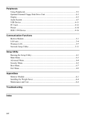
Peripherals Using Peripherals...4-1 Optional External Floppy Disk Drive Unit 4-3 Display...4-5 Audio System ...4-7 USB Device ...4-11 PC Card...4-12 Printer ...4-14 IEEE 1394 Device 4-16 Communication Functions Built-in Modem ...5-1 LAN unit...5-4 Wireless LAN ...5-7 Network Setup Utility 5-11 Setup Utility Running the Setup Utility 6-1 Main Menu ...6-3 Advanced Menu...6-4 Security Menu...6-5 Boot Menu ...6-7 Exit Menu ...6-8 Appendixes Memory Module ...A-1 Installing the Weight Saver A-4 Maintenance and Care A-6 Troubleshooting Index xvi
Peripherals Using Peripherals...4-1 Optional External Floppy Disk Drive Unit 4-3 Display...4-5 Audio System ...4-7 USB Device ...4-11 PC Card...4-12 Printer ...4-14 IEEE 1394 Device 4-16 Communication Functions Built-in Modem ...5-1 LAN unit...5-4 Wireless LAN ...5-7 Network Setup Utility 5-11 Setup Utility Running the Setup Utility 6-1 Main Menu ...6-3 Advanced Menu...6-4 Security Menu...6-5 Boot Menu ...6-7 Exit Menu ...6-8 Appendixes Memory Module ...A-1 Installing the Weight Saver A-4 Maintenance and Care A-6 Troubleshooting Index xvi
Operation Manual
Page 94
...controller version of your computer. Press Enter to 640KB. An external keyboard will turn when Fn+NumLk are pressed regardless of the internal memory while booting, to shorten the boot time. 6 Quiet Boot defines whether the SHARP logo appears on the CPU. Video RAM Size shows the minimum size of the extended... memory more than 1MB. Always set to show the details. Use Tab key to move the cursor, and minus key or space bar to ...
...controller version of your computer. Press Enter to 640KB. An external keyboard will turn when Fn+NumLk are pressed regardless of the internal memory while booting, to shorten the boot time. 6 Quiet Boot defines whether the SHARP logo appears on the CPU. Video RAM Size shows the minimum size of the extended... memory more than 1MB. Always set to show the details. Use Tab key to move the cursor, and minus key or space bar to ...
Operation Manual
Page 100
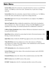
...8226; After a long usage of your computer. For available memory modules, contact your computer and remove the AC adapter. See Chapter 3 for the default memory size of your body by the edges. • Keep the memory module in the location where static electricity is expandable. A-1 Appendixes... the AC adapter and remove the battery pack and peripheral devices. Memory Module You can install a memory module into some models and upgrade the memory size. Installing a Memory Module • Do not handle the memory module in the anti-static wrapping until it is easily generated such...
...8226; After a long usage of your computer. For available memory modules, contact your computer and remove the AC adapter. See Chapter 3 for the default memory size of your body by the edges. • Keep the memory module in the location where static electricity is expandable. A-1 Appendixes... the AC adapter and remove the battery pack and peripheral devices. Memory Module You can install a memory module into some models and upgrade the memory size. Installing a Memory Module • Do not handle the memory module in the anti-static wrapping until it is easily generated such...
Operation Manual
Page 101
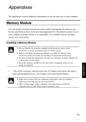
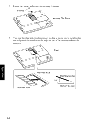
Sheet Notched Part Projected Part Memory Module 20° Memory Socket Appendixes A-2 2. Screws Memory Slot Cover 3. Turn over the sheet and align the memory module as shown below, matching the notched part of the module with the projected part of the memory socket of the computer. Loosen two screws and remove the memory slot cover.
Sheet Notched Part Projected Part Memory Module 20° Memory Socket Appendixes A-2 2. Screws Memory Slot Cover 3. Turn over the sheet and align the memory module as shown below, matching the notched part of the module with the projected part of the memory socket of the computer. Loosen two screws and remove the memory slot cover.
Operation Manual
Page 102
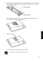
Tighten the screws. 7. A-3 Appendixes Replace the sheet and memory slot cover, matching the projected parts of the cover with the projected parts of the computer. 6. See Chapter 3 for replacing the battery pack. Notched Parts Projected Part 5. Replace the battery pack and connect the AC adapter. Press the memory module slowly to place it into the memory socket, matching the notched parts of the module with the notched parts of the socket, until you hear the clicking sound. 4.
Tighten the screws. 7. A-3 Appendixes Replace the sheet and memory slot cover, matching the projected parts of the cover with the projected parts of the computer. 6. See Chapter 3 for replacing the battery pack. Notched Parts Projected Part 5. Replace the battery pack and connect the AC adapter. Press the memory module slowly to place it into the memory socket, matching the notched parts of the module with the notched parts of the socket, until you hear the clicking sound. 4.
Operation Manual
Page 103
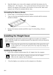
...You can get the better portability. Make sure to make your computer and remove the AC adapter. by clicking start - Your memory size appears at the bottom of Installing a Memory Module. Latches 3. Turn off your computer lighter. A-4 Appendixes Always keep the optical drive bay installed either of the optical ... change the optical drive unit for the weight saver to turn over the sheet and slightly bend both latches outwards until the memory module is released. turn on a flat place. Leaving the optical drive bay empty may be included with the value. Uninstalling the...
...You can get the better portability. Make sure to make your computer and remove the AC adapter. by clicking start - Your memory size appears at the bottom of Installing a Memory Module. Latches 3. Turn off your computer lighter. A-4 Appendixes Always keep the optical drive bay installed either of the optical ... change the optical drive unit for the weight saver to turn over the sheet and slightly bend both latches outwards until the memory module is released. turn on a flat place. Leaving the optical drive bay empty may be included with the value. Uninstalling the...
Operation Manual
Page 123
... device connecting, 4-16 disconnecting, 4-17 Indicators antenna, 5-7 battery, 2-1 power, 2-1 status, xvii K Keyboard function keys, 2-6 special keys, 2-6 troubleshooting, T-4 windows key, 2-6 L LAN configuring, 5-6 connecting to network, 5-4 troubleshooting, T-8 M Memory module installing, A-1 uninstalling, A-4 Modem configuring, 5-3 connecting to telephone line, 5-2 Index-2 troubleshooting, T-7 N Network setup utility changing, 5-12 deleting, 5-12 loading, 5-11 switching, 5-11 O Optical drive troubleshooting...
... device connecting, 4-16 disconnecting, 4-17 Indicators antenna, 5-7 battery, 2-1 power, 2-1 status, xvii K Keyboard function keys, 2-6 special keys, 2-6 troubleshooting, T-4 windows key, 2-6 L LAN configuring, 5-6 connecting to network, 5-4 troubleshooting, T-8 M Memory module installing, A-1 uninstalling, A-4 Modem configuring, 5-3 connecting to telephone line, 5-2 Index-2 troubleshooting, T-7 N Network setup utility changing, 5-12 deleting, 5-12 loading, 5-11 switching, 5-11 O Optical drive troubleshooting...