Operating Instructions
Page 3
... be determined by turning the equipment off and on a circuit different from that interference will not occur in CANADA This Class B digital apparatus complies with the limits for help. If this device must accept any interference received, including interference that may not cause harmful ... ICES-003. Reorient or relocate the receiving antenna. - Consult the dealer or an experienced radio/TV technician for a Class B digital device, pursuant to provide reasonable protection against harmful interference in CANADA CAUTION TO PREVENT ELECTRIC SHOCK, MATCH WIDE BLADE OF PLUG TO ...
... be determined by turning the equipment off and on a circuit different from that interference will not occur in CANADA This Class B digital apparatus complies with the limits for help. If this device must accept any interference received, including interference that may not cause harmful ... ICES-003. Reorient or relocate the receiving antenna. - Consult the dealer or an experienced radio/TV technician for a Class B digital device, pursuant to provide reasonable protection against harmful interference in CANADA CAUTION TO PREVENT ELECTRIC SHOCK, MATCH WIDE BLADE OF PLUG TO ...
Operating Instructions
Page 5
... Quick Reference Identifying the parts and controls .... 145 Quick Function Guide 153 Index 154 • Windows® is trademark of Apple Computer, Inc. •All other countries. •Macintosh is registered trademark or trademark of their respective companies. Standard print ........ 112 Making prints of contents Printing operations (DCR-TRV820 only) Using the printer...
... Quick Reference Identifying the parts and controls .... 145 Quick Function Guide 153 Index 154 • Windows® is trademark of Apple Computer, Inc. •All other countries. •Macintosh is registered trademark or trademark of their respective companies. Standard print ........ 112 Making prints of contents Printing operations (DCR-TRV820 only) Using the printer...
Operating Instructions
Page 12
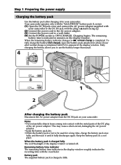
...pack in the display window. Remaining battery time indicator The remaining battery time indicator in the display window roughly indicates the recording time with the metal parts of the DC plug of the display window is completed. Notes •Prevent metallic objects from the DC IN jack ...for a long time, charge the battery pack once fully, and then use the battery longer than usual. 4 VTR OFF (CHARGE) MEMORY CAMERA 1 2 After charging the battery pack Disconnect the AC power adaptor from coming into contact with the viewfinder. Charging begins. Your camcorder operates only...
...pack in the display window. Remaining battery time indicator The remaining battery time indicator in the display window roughly indicates the recording time with the metal parts of the DC plug of the display window is completed. Notes •Prevent metallic objects from the DC IN jack ...for a long time, charge the battery pack once fully, and then use the battery longer than usual. 4 VTR OFF (CHARGE) MEMORY CAMERA 1 2 After charging the battery pack Disconnect the AC power adaptor from coming into contact with the viewfinder. Charging begins. Your camcorder operates only...
Operating Instructions
Page 16
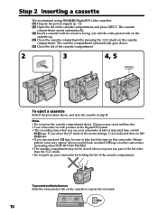
...Do not pick up . (4) Close the cassette compartment by holding the lid of the lid other DCR-TRV720/TRV820). •The cassette compartment may cause malfunction. •Your camcorder records pictures in the menu settings, 3/4 of indicated time on the cassette to expose the red mark.... select the LP mode in the Digital8 system. • The recording time when you use standard 8 tape, be closed when you press any part of the cassette compartment. Step 2 Inserting a cassette We recommend using Hi8 /Digital8 video cassettes. (1) Prepare the power supply (p. 11). (2) Open the...
...Do not pick up . (4) Close the cassette compartment by holding the lid of the lid other DCR-TRV720/TRV820). •The cassette compartment may cause malfunction. •Your camcorder records pictures in the menu settings, 3/4 of indicated time on the cassette to expose the red mark.... select the LP mode in the Digital8 system. • The recording time when you use standard 8 tape, be closed when you press any part of the cassette compartment. Step 2 Inserting a cassette We recommend using Hi8 /Digital8 video cassettes. (1) Prepare the power supply (p. 11). (2) Open the...
Operating Instructions
Page 48
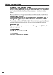
... and Russian characters appear. Select [ to the previous screen. ] to delete the title. To enter a space Select [Z& ?!], then select the blank part. 48 We recommend setting the POWER switch to CAMERA again, then proceed from step 1. Enter the new title as desired. If you are entering title characters. Turn the SEL/PUSH...
... and Russian characters appear. Select [ to the previous screen. ] to delete the title. To enter a space Select [Z& ?!], then select the blank part. 48 We recommend setting the POWER switch to CAMERA again, then proceed from step 1. Enter the new title as desired. If you are entering title characters. Turn the SEL/PUSH...
Operating Instructions
Page 74
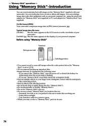
...;Stick its case. 74 Extremely hot such as a personal computer etc., using "Memory Stick" Terminal Write-protect tab Labeling position •You cannot record or erase still images when the write-protect tab on the "Memory Stick" is flashing - If you use or keep "Memory Stick"s in the...use "Memory Stick"s near static electricity or magnetic fields. •Prevent metallic objects or your finger from coming into contact with the metal parts of your personal computer. Typical image data file name 100-0001: This file name appears on the display of your camcorder. Very humid ...
...;Stick its case. 74 Extremely hot such as a personal computer etc., using "Memory Stick" Terminal Write-protect tab Labeling position •You cannot record or erase still images when the write-protect tab on the "Memory Stick" is flashing - If you use or keep "Memory Stick"s in the...use "Memory Stick"s near static electricity or magnetic fields. •Prevent metallic objects or your finger from coming into contact with the metal parts of your personal computer. Typical image data file name 100-0001: This file name appears on the display of your camcorder. Very humid ...
Operating Instructions
Page 85
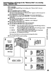
... Stick" into your camcorder. (1) Set the POWER switch to be swapped with a still image M. The last recorded still image on "Memory Stick" appears on the lower part of the area in the still image which is to CAMERA. (2) Press MEMORY MIX in the standby mode. CHROM y M. OVERLAP (5) Press the SEL/PUSH EXEC dial...
... Stick" into your camcorder. (1) Set the POWER switch to be swapped with a still image M. The last recorded still image on "Memory Stick" appears on the lower part of the area in the still image which is to CAMERA. (2) Press MEMORY MIX in the standby mode. CHROM y M. OVERLAP (5) Press the SEL/PUSH EXEC dial...
Operating Instructions
Page 109
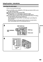
... that the print surface is facing towards you. Insert the print paper until less than 3 cm Printing operations 109 Press the print paper into the part of the arrow to MEMORY or VTR. The print paper starts to be automatically drawn in. 3 PRINT PAPER lamp PRINT CARTRIDGE lamp PRINT lamp Printer...
... that the print surface is facing towards you. Insert the print paper until less than 3 cm Printing operations 109 Press the print paper into the part of the arrow to MEMORY or VTR. The print paper starts to be automatically drawn in. 3 PRINT PAPER lamp PRINT CARTRIDGE lamp PRINT lamp Printer...
Operating Instructions
Page 118
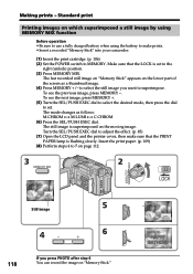
to select the still image you press PHOTO after step 6 You can record the image on the lower part of the screen as follows: M.CHROM y M.LUMI y C.CHROM (6) Press the SEL/PUSH EXEC ... Perform steps 4 to adjust the effect. (p. 85) (7) Open the LCD panel and the printer cover, then make prints. •Insert a recorded "Memory Stick" into your camcorder. (1) Insert the print cartridge. (p. 106) (2) Set the POWER switch to superimpose. M. The still image is...is superimposed on page 112. 3 2 MEMORY MIX VTR OFF (CHARGE) MEMORY CAMERA M. To see the previous image, press MEMORY -.
to select the still image you press PHOTO after step 6 You can record the image on the lower part of the screen as follows: M.CHROM y M.LUMI y C.CHROM (6) Press the SEL/PUSH EXEC ... Perform steps 4 to adjust the effect. (p. 85) (7) Open the LCD panel and the printer cover, then make prints. •Insert a recorded "Memory Stick" into your camcorder. (1) Insert the print cartridge. (p. 106) (2) Set the POWER switch to superimpose. M. The still image is...is superimposed on page 112. 3 2 MEMORY MIX VTR OFF (CHARGE) MEMORY CAMERA M. To see the previous image, press MEMORY -.

Operating Instructions
Page 140
...Sony service facility and inform them of dirt on the platen roller Printed images may not be reduced by one after cleaning the platen roller. Note that insert the platen roller cleaner instead of print paper in the paper feeder. • Insert the platen roller cleaner vertically against the body. Cleaner part...information and precautions - How to clean the platen roller Perform steps 1 to 7 on the platen roller which it will be clear. DCR-TRV820 only About the influence of the following product numbers: • Head cleaner (1-772-863-11) • Platen roller cleaner (1-772-862...
...Sony service facility and inform them of dirt on the platen roller Printed images may not be reduced by one after cleaning the platen roller. Note that insert the platen roller cleaner instead of print paper in the paper feeder. • Insert the platen roller cleaner vertically against the body. Cleaner part...information and precautions - How to clean the platen roller Perform steps 1 to 7 on the platen roller which it will be clear. DCR-TRV820 only About the influence of the following product numbers: • Head cleaner (1-772-863-11) • Platen roller cleaner (1-772-862...

Operating Instructions
Page 142
... from battery leakage or corrosion, observe the following: - Dusty or dirty - Vibrating Battery pack •Use only the specified charger or video equipment with the charging function. •To prevent accident from a short circuit, do not allow metal objects to insert the batteries with ...on dry batteries To avoid possible damage from coming into your eyes, wash your nearest Sony dealer. 142 polarities matched to any problem occurs, unplug your camcorder and contact your eyes with the metal parts of water and then consult a doctor. Dry batteries are : - Do not use...
... from battery leakage or corrosion, observe the following: - Dusty or dirty - Vibrating Battery pack •Use only the specified charger or video equipment with the charging function. •To prevent accident from a short circuit, do not allow metal objects to insert the batteries with ...on dry batteries To avoid possible damage from coming into your eyes, wash your nearest Sony dealer. 142 polarities matched to any problem occurs, unplug your camcorder and contact your eyes with the metal parts of water and then consult a doctor. Dry batteries are : - Do not use...
Operating Instructions
Page 144
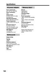
... (approx.) 0.14 oz (4 g) Design and specifications are subject to +60 °C) Dimensions (approx.) 5 × 1 9/16 × 2 1/2 in. (125 × 39 × 62 mm) (w/h/d) excluding projecting parts Mass (approx.) 9.8 oz (280 g) excluding power cord "Memory Stick" Memory Flash memory 4MB: MSA-4A Operating voltage 2.7 - 3.6 V Power consumption Approx. 45 mA in the operating...
... (approx.) 0.14 oz (4 g) Design and specifications are subject to +60 °C) Dimensions (approx.) 5 × 1 9/16 × 2 1/2 in. (125 × 39 × 62 mm) (w/h/d) excluding projecting parts Mass (approx.) 9.8 oz (280 g) excluding power cord "Memory Stick" Memory Flash memory 4MB: MSA-4A Operating voltage 2.7 - 3.6 V Power consumption Approx. 45 mA in the operating...

Operating Instructions
Page 145
Quick Reference - Identifying the parts and controls Camcorder VTR 4 OFF (CHARGE) MEMORY CAMERA 5 1 6 2 7 3 8 1 LCD BRIGHT buttons (p. 18) 2 OPEN button (p. 17) 3 VOLUME buttons (p. 25) 4 START/STOP button (p. 17) 5 POWER switch (p. 17) 6 BATT RELEASE lever (p. 11) 7 Hooks for Sony video products. When purchasing Sony video products, Sony recommends that you purchase accessories with this product is a genuine accessory for shoulder strap (p. 147) 8 DC IN jack (p. 12) This mark indicates that this "GENUINE VIDEO ACCESSORIES" mark. Quick Reference 145 -
Quick Reference - Identifying the parts and controls Camcorder VTR 4 OFF (CHARGE) MEMORY CAMERA 5 1 6 2 7 3 8 1 LCD BRIGHT buttons (p. 18) 2 OPEN button (p. 17) 3 VOLUME buttons (p. 25) 4 START/STOP button (p. 17) 5 POWER switch (p. 17) 6 BATT RELEASE lever (p. 11) 7 Hooks for Sony video products. When purchasing Sony video products, Sony recommends that you purchase accessories with this product is a genuine accessory for shoulder strap (p. 147) 8 DC IN jack (p. 12) This mark indicates that this "GENUINE VIDEO ACCESSORIES" mark. Quick Reference 145 -
Operating Instructions
Page 146
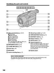
...video equipment having the super laser link mark by using infrared rays. 146 EDITSEARCH buttons (p. 24) qa S.LASER LINK button (p. 29) qs Focus ring (p. 44) qd Microphone qf Camera recording... lamp (p. 17) qg Infrared rays emitter (p. 21, 29) qh SUPER NIGHTSHOT button (p. 21) qj NIGHTSHOT switch (p. 21) qk Display window (p. 152) ql FOCUS switch (p. 44) w; qg wa 9 Video control ...buttons (p. 25, 27) x STOP (stop) m REW (rewind) N PLAY (playback) M FF (fastforward) X PAUSE (pause) z REC (recording) The control buttons light up...
...video equipment having the super laser link mark by using infrared rays. 146 EDITSEARCH buttons (p. 24) qa S.LASER LINK button (p. 29) qs Focus ring (p. 44) qd Microphone qf Camera recording... lamp (p. 17) qg Infrared rays emitter (p. 21, 29) qh SUPER NIGHTSHOT button (p. 21) qj NIGHTSHOT switch (p. 21) qk Display window (p. 152) ql FOCUS switch (p. 44) w; qg wa 9 Video control ...buttons (p. 25, 27) x STOP (stop) m REW (rewind) N PLAY (playback) M FF (fastforward) X PAUSE (pause) z REC (recording) The control buttons light up...
Operating Instructions
Page 147
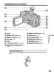
Identifying the parts and controls ws wk wd wf wl e; Quick Reference 147 FADER button (p. 34) ea BACK LIGHT button (p. 21) es PROGRAM AE button (p. 41) ed EXPOSURE button (p. 43) ef MEMORY MIX button (p. 84) Attaching the shoulder strap Attach the shoulder strap supplied with your camcorder to the hooks for the shoulder strap. button (p. 85, 91) wg LCD screen (p. 18) wh Speaker wj (self-timer) button (p. 23, 31, 83) wk Viewfinder lens adjustment lever (p. 20) wl MEMORY DELETE button (p. 100) e; wg ea es ed wh ef wj ws Eyecup wd MEMORY PLAY button (p. 91) wf MEMORY -
Identifying the parts and controls ws wk wd wf wl e; Quick Reference 147 FADER button (p. 34) ea BACK LIGHT button (p. 21) es PROGRAM AE button (p. 41) ed EXPOSURE button (p. 43) ef MEMORY MIX button (p. 84) Attaching the shoulder strap Attach the shoulder strap supplied with your camcorder to the hooks for the shoulder strap. button (p. 85, 91) wg LCD screen (p. 18) wh Speaker wj (self-timer) button (p. 23, 31, 83) wk Viewfinder lens adjustment lever (p. 20) wl MEMORY DELETE button (p. 100) e; wg ea es ed wh ef wj ws Eyecup wd MEMORY PLAY button (p. 91) wf MEMORY -
Operating Instructions
Page 148
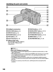
...turn the power supplied by the shoe on the intelligent accessory shoe •The intelligent accessory shoe supplies power to optional accessories such as a video light or microphone. •The intelligent accessory shoe is in the "Memory Stick" compartment. Refer to the end, and then tighten the ... button (p. 26) ej DISPLAY button (p. 26) ek PB ZOOM button (p. 52, 96) el TITLE button (p. 45) r; Identifying the parts and controls eg r; rs PHOTO button (p. 30, 79) rd DIGITAL EFFECT button (p. 39, 51) rf END SEARCH button (p. 24) rg PICTURE EFFECT button (p. 37, 50) rh MENU button (p. 33,...
...turn the power supplied by the shoe on the intelligent accessory shoe •The intelligent accessory shoe supplies power to optional accessories such as a video light or microphone. •The intelligent accessory shoe is in the "Memory Stick" compartment. Refer to the end, and then tighten the ... button (p. 26) ej DISPLAY button (p. 26) ek PB ZOOM button (p. 52, 96) el TITLE button (p. 45) r; Identifying the parts and controls eg r; rs PHOTO button (p. 30, 79) rd DIGITAL EFFECT button (p. 39, 51) rf END SEARCH button (p. 24) rg PICTURE EFFECT button (p. 37, 50) rh MENU button (p. 33,...
Operating Instructions
Page 149
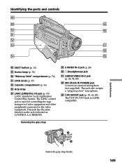
.... tl DV IN/OUT jack (p. 59, 62, 88) The DV IN/OUT jack is used for Local Application Control Bus System. Identifying the parts and controls rk rl tg t; This jack also accepts a "plug-in-power" microphone. The LANC control jack is i.LINK compatible. Fastening the...77) ts Cassette compartment (p. 16) td Grip strap tf LANC /DIGITAL I/O jack (p. 93) LANC stands for controlling the tape transport of video equipment and other peripherals connected to the video equipment. tg S VIDEO ID-2 jack (p. 28) th i (headphones) jack tj AUDIO/VIDEO ID-2 jack (p. 28, 58, 88) tk MIC (PLUG IN...
.... tl DV IN/OUT jack (p. 59, 62, 88) The DV IN/OUT jack is used for Local Application Control Bus System. Identifying the parts and controls rk rl tg t; This jack also accepts a "plug-in-power" microphone. The LANC control jack is i.LINK compatible. Fastening the...77) ts Cassette compartment (p. 16) td Grip strap tf LANC /DIGITAL I/O jack (p. 93) LANC stands for controlling the tape transport of video equipment and other peripherals connected to the video equipment. tg S VIDEO ID-2 jack (p. 28) th i (headphones) jack tj AUDIO/VIDEO ID-2 jack (p. 28, 58, 88) tk MIC (PLUG IN...
Operating Instructions
Page 150
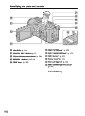
ya ys yf yg yh yj yk yl u; PRINT CARTRIDGE OPEN knob* (p. 106) * DCR-TRV820 only 150 Viewfinder (p. 20) ya MEMORY INDEX button (p. 92) ys Lithium battery compartment (p. 126) yd MEMORY + button (p. 85, 91) yf PRINT lamp* (p. 105) yg PRINT PAPER lamp* (p. 105) yh PRINT CARTRIDGE lamp* (p. 105) yj PRINT button* (p. 105) yk Printer cover* (p. 109) yl Print cartridge lid* (p. 106) u; Identifying the parts and controls y; yd y;
ya ys yf yg yh yj yk yl u; PRINT CARTRIDGE OPEN knob* (p. 106) * DCR-TRV820 only 150 Viewfinder (p. 20) ya MEMORY INDEX button (p. 92) ys Lithium battery compartment (p. 126) yd MEMORY + button (p. 85, 91) yf PRINT lamp* (p. 105) yg PRINT PAPER lamp* (p. 105) yh PRINT CARTRIDGE lamp* (p. 105) yj PRINT button* (p. 105) yk Printer cover* (p. 109) yl Print cartridge lid* (p. 106) u; Identifying the parts and controls y; yd y;
Operating Instructions
Page 151
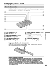
Identifying the parts and controls Remote Commander The buttons that have the same name on the Remote Commander as direct sunlight or overhead lighting. polarities on the batteries to control the camcorder after turning on your camcorder from other Sony VCRs to avoid remote control misoperation. If you use another Sony VCR in the...
Identifying the parts and controls Remote Commander The buttons that have the same name on the Remote Commander as direct sunlight or overhead lighting. polarities on the batteries to control the camcorder after turning on your camcorder from other Sony VCRs to avoid remote control misoperation. If you use another Sony VCR in the...

Operating Instructions
Page 152
...(p. 133)/Remaining battery time indicator (p. 12) wg FULL charge indicator (p. 12) Identifying the parts and controls Operation indicators LCD screen and Viewfinder Display window 1 qf ws 2 2 3 qg...time indicator (p. 12, 20) 4 Zoom indicator (p. 19)/Exposure indicator (p. 43) 5 Fader indicator (p. 35)/Digital effect indicator (p. 39, 51) 6 Wide mode indicator (p. 33)/ FRAME indicator (p. 69) 7 Picture effect ...17)/Video control mode (p. 27) 152 qg Tape counter indicator (p. 20, 49, 53)/ Time code indicator (p. 20)/ Self-diagnosis display indicator (p. 133)/Tape photo recording indicator...
...(p. 133)/Remaining battery time indicator (p. 12) wg FULL charge indicator (p. 12) Identifying the parts and controls Operation indicators LCD screen and Viewfinder Display window 1 qf ws 2 2 3 qg...time indicator (p. 12, 20) 4 Zoom indicator (p. 19)/Exposure indicator (p. 43) 5 Fader indicator (p. 35)/Digital effect indicator (p. 39, 51) 6 Wide mode indicator (p. 33)/ FRAME indicator (p. 69) 7 Picture effect ...17)/Video control mode (p. 27) 152 qg Tape counter indicator (p. 20, 49, 53)/ Time code indicator (p. 20)/ Self-diagnosis display indicator (p. 133)/Tape photo recording indicator...


