
Instruction Manual
Page 13
Preparing the camera Preparing the camera Checking the accessories supplied The number in parentheses indicates the number of pieces. • BC-VM10 Battery charger (1)/ Power cord (mains lead) (1) • Rechargeable battery pack NPFM500H (1) • Eyecup (1) (Attached on the camera) • CD-ROM (Application Software for α camera) (1) • Quick Start Guide (1) • Instruction Manual (This manual) (1) • USB cable (1) • Video cable (1) • Shoulder strap (1) • Eyepiece cover (1) • Body cap (1) (Attached on the camera) 13
Preparing the camera Preparing the camera Checking the accessories supplied The number in parentheses indicates the number of pieces. • BC-VM10 Battery charger (1)/ Power cord (mains lead) (1) • Rechargeable battery pack NPFM500H (1) • Eyecup (1) (Attached on the camera) • CD-ROM (Application Software for α camera) (1) • Quick Start Guide (1) • Instruction Manual (This manual) (1) • USB cable (1) • Video cable (1) • Shoulder strap (1) • Eyepiece cover (1) • Body cap (1) (Attached on the camera) 13

Instruction Manual
Page 27
...and the eyepiece cover. Eyepiece cover Using the eyepiece cover You can also attach the eyepiece cover (below) on the strap. Preparing the camera Using the accessories supplied This section describes how to use of the viewfinder, as in the following pages. • Rechargeable battery pack (page...14) • Eyecup (page 26) • USB cable (pages 120, 136) • Video cable (page 104) • CD-ROM (page 128) Attaching the shoulder strap Attach the both ends of the strap on the camera. • You can prevent light from entering through the viewfinder and affecting the exposure.
...and the eyepiece cover. Eyepiece cover Using the eyepiece cover You can also attach the eyepiece cover (below) on the strap. Preparing the camera Using the accessories supplied This section describes how to use of the viewfinder, as in the following pages. • Rechargeable battery pack (page...14) • Eyecup (page 26) • USB cable (pages 120, 136) • Video cable (page 104) • CD-ROM (page 128) Attaching the shoulder strap Attach the both ends of the strap on the camera. • You can prevent light from entering through the viewfinder and affecting the exposure.

Instruction Manual
Page 36
Sides/Bottom A VIDEO OUT/USB terminal (104, 120) B Memory card cover C Memory card insertion slot (21) D Memory card eject lever (22) E Hooks for shoulder strap (27) F REMOTE terminal • When connecting the RMS1AM/RM-L1AM Remote Commander (not supplied) to the camera, insert the plug of the ...terminal on the guide of less than 5.5 mm (7/32 inch), and may damage the camera. G DC IN terminal • When connecting the ACVQ900AM AC Adaptor/ Charger (not supplied) to the camera, turn the camera off, then plug the connector of the AC Adaptor/Charger to tripods having screws longer...
Sides/Bottom A VIDEO OUT/USB terminal (104, 120) B Memory card cover C Memory card insertion slot (21) D Memory card eject lever (22) E Hooks for shoulder strap (27) F REMOTE terminal • When connecting the RMS1AM/RM-L1AM Remote Commander (not supplied) to the camera, insert the plug of the ...terminal on the guide of less than 5.5 mm (7/32 inch), and may damage the camera. G DC IN terminal • When connecting the ACVQ900AM AC Adaptor/ Charger (not supplied) to the camera, turn the camera off, then plug the connector of the AC Adaptor/Charger to tripods having screws longer...
Instruction Manual
Page 104
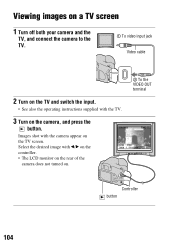
Images shot with the camera appear on the camera, and press the button. Viewing images on a TV screen 1 Turn off both your camera and the TV, and connect the camera to the TV. 1 To video input jack Video cable 2 Turn on the TV and switch the input. • See also the operating instructions supplied with the TV. 3 Turn on the TV screen. Select the desired image with b/B on the controller. • The LCD monitor on the rear of the camera does not turned on. 2 To the VIDEO OUT terminal Controller button 104
Images shot with the camera appear on the camera, and press the button. Viewing images on a TV screen 1 Turn off both your camera and the TV, and connect the camera to the TV. 1 To video input jack Video cable 2 Turn on the TV and switch the input. • See also the operating instructions supplied with the TV. 3 Turn on the TV screen. Select the desired image with b/B on the controller. • The LCD monitor on the rear of the camera does not turned on. 2 To the VIDEO OUT terminal Controller button 104

Instruction Manual
Page 105
...system of the TV must match that of your digital still camera. PAL-M system Brazil PAL-N system Argentina, Paraguay, Uruguay SECAM system Bulgaria, France, Guiana, Iran, Iraq, Monaco, Russia, Ukraine, etc. Using the viewing function 105 Sets the video output signal to PAL mode (e.g., for the TV ...color system of the country or region where the camera is used. Check the following lists for Europe). NTSC system Bahama Islands, Bolivia, Canada, ...
...system of the TV must match that of your digital still camera. PAL-M system Brazil PAL-N system Argentina, Paraguay, Uruguay SECAM system Bulgaria, France, Guiana, Iran, Iraq, Monaco, Russia, Ukraine, etc. Using the viewing function 105 Sets the video output signal to PAL mode (e.g., for the TV ...color system of the country or region where the camera is used. Check the following lists for Europe). NTSC system Bahama Islands, Bolivia, Canada, ...

Instruction Manual
Page 147
... it . Computers You do not want to delete (page 101). The image does not appear on the TV screen. • Check [Video output] to see if the video output signal of your camera is set to the color system of your TV (page 105). • Check whether the connection is compatible with the... camera. • Check "Recommended computer environment" (pages 119, 127). You have deleted an image by mistake. • Once you have deleted an ...
... it . Computers You do not want to delete (page 101). The image does not appear on the TV screen. • Check [Video output] to see if the video output signal of your camera is set to the color system of your TV (page 105). • Check whether the connection is compatible with the... camera. • Check "Recommended computer environment" (pages 119, 127). You have deleted an image by mistake. • Once you have deleted an ...

Instruction Manual
Page 158
... ........ 46 U USB connection 120, 136 R RAW 106, 131 Rear sync 74 Rec mode reset 116 Red eye reduc 73 Reducing camera shake 45 Reset 116 Reset default 117 Rotate 94 V Video output 105 Viewfinder 26, 40 Viewing image 93, 104 W White balance 83 White balance bracket 92 Wireless flash 74 S Saturation 87...
... ........ 46 U USB connection 120, 136 R RAW 106, 131 Rear sync 74 Rec mode reset 116 Red eye reduc 73 Reducing camera shake 45 Reset 116 Reset default 117 Rotate 94 V Video output 105 Viewfinder 26, 40 Viewing image 93, 104 W White balance 83 White balance bracket 92 Wireless flash 74 S Saturation 87...


