
Operating Instructions
Page 24
...unit.) • Even when the DSR-45 plays back a PAL formatted tape (or the DSR-45P plays back an NTSC formatted tape), you can control the basic tape transport functions using a device connected to the RS-232C connector 1 or the RS-422A connector 2. Note For editing, if you also need to use... unit has a SHUTTLE A/B switching function and a LANC-M function, set the LANC mode on the recorder to control this unit. However, editing operations attempted in this case are not guaranteed. • For editing, if you intend to use this unit as a player and the FXE-120/120P or FXE-100/100P as an...
...unit.) • Even when the DSR-45 plays back a PAL formatted tape (or the DSR-45P plays back an NTSC formatted tape), you can control the basic tape transport functions using a device connected to the RS-232C connector 1 or the RS-422A connector 2. Note For editing, if you also need to use... unit has a SHUTTLE A/B switching function and a LANC-M function, set the LANC mode on the recorder to control this unit. However, editing operations attempted in this case are not guaranteed. • For editing, if you intend to use this unit as a player and the FXE-120/120P or FXE-100/100P as an...

Operating Instructions
Page 33
... codes as a stand-alone videocassette player. Set the INPUT SELECT selector to a position where a signal is automatically detected so you are using the unit as part of an editing system, for input and output. Chapter 2 Playback and Recording Playback This section describes the connections,...DSR-45/45P (rear panel) i.LINK cable (DV cable) (not supplied) DV jack Notes • With the DV connection, data codes (recording date/ time, camera data) recorded on the VTR SET menu to make separate connections for dubbing, or as those recorded on the source tape are displayed on the VIDEO...
... codes as a stand-alone videocassette player. Set the INPUT SELECT selector to a position where a signal is automatically detected so you are using the unit as part of an editing system, for input and output. Chapter 2 Playback and Recording Playback This section describes the connections,...DSR-45/45P (rear panel) i.LINK cable (DV cable) (not supplied) DV jack Notes • With the DV connection, data codes (recording date/ time, camera data) recorded on the VTR SET menu to make separate connections for dubbing, or as those recorded on the source tape are displayed on the VIDEO...

Operating Instructions
Page 34
... Phono jack cable (not supplied) Phono jack cable (not supplied) Audio input Video input DSR-45/45P (player) (rear panel) Reference video signal generator B.B.OUT B.B.OUT 75 Ω coaxial cable (not supplied) REF.VIDEO Monitor Recorder S-video input S-video cable (not supplied) 75 Ω coaxial cable (not supplied) Video cable (3BNC y 3BNC) (not supplied) Audio cable (XLR y XLR) (not supplied...
... Phono jack cable (not supplied) Phono jack cable (not supplied) Audio input Video input DSR-45/45P (player) (rear panel) Reference video signal generator B.B.OUT B.B.OUT 75 Ω coaxial cable (not supplied) REF.VIDEO Monitor Recorder S-video input S-video cable (not supplied) 75 Ω coaxial cable (not supplied) Video cable (3BNC y 3BNC) (not supplied) Audio cable (XLR y XLR) (not supplied...

Operating Instructions
Page 41
...connections for dubbing or as those recorded on the monitor screen. However, the contents of the source tape. Monitor DSR-45/45P (rear panel) i.LINK cable (DV cable) (not supplied) DV jack Digital video equipment with hardly any degradation, enabling high-quality recording. If you connect or disconnect the...operations apply whether you do not need to the input connectors of a player or that has a 6-pin DV jack to this unit, which may cause a malfunction. • If DV input has been selected, the video signal output from the AC outlet beforehand. Disconnect the cables. 41 ...
...connections for dubbing or as those recorded on the monitor screen. However, the contents of the source tape. Monitor DSR-45/45P (rear panel) i.LINK cable (DV cable) (not supplied) DV jack Digital video equipment with hardly any degradation, enabling high-quality recording. If you connect or disconnect the...operations apply whether you do not need to the input connectors of a player or that has a 6-pin DV jack to this unit, which may cause a malfunction. • If DV input has been selected, the video signal output from the AC outlet beforehand. Disconnect the cables. 41 ...

Operating Instructions
Page 42
... jack You can be distorted. Monitor Player S-video output Video output Audio output Component output Monitor Phono jack cable (not supplied) Audio input Video input DSR-45/45P (recorder) (rear panel) Phono jack cable (not supplied) S-video cable (not supplied) 75 Ω coaxial cable (not supplied) Audio cable (phono jack) (not supplied) Video cable (3BNC y 3BNC) (not supplied) : Signal...
... jack You can be distorted. Monitor Player S-video output Video output Audio output Component output Monitor Phono jack cable (not supplied) Audio input Video input DSR-45/45P (recorder) (rear panel) Phono jack cable (not supplied) S-video cable (not supplied) 75 Ω coaxial cable (not supplied) Audio cable (phono jack) (not supplied) Video cable (3BNC y 3BNC) (not supplied) : Signal...

Operating Instructions
Page 48
... 3 Using the Unit as a Player in an Editing System DV 2 Editing controller DV jack If the editing software used , refer to the instruction manual of the editing software. Edit functions are specified by the editing software. If you connect or disconnect...editing controller via DV jacks to record the time code, set DV IN TC on page 78 (GB). 1 Phono jack cable (not supplied) 2 i.LINK cable (DV cable) (not supplied) Note If the unit is output from the digital non-linear editing controller to this unit, and you use. DSR-45/45P MONITOR VIDEO MONITOR AUDIO 1 Video input Video...
... 3 Using the Unit as a Player in an Editing System DV 2 Editing controller DV jack If the editing software used , refer to the instruction manual of the editing software. Edit functions are specified by the editing software. If you connect or disconnect...editing controller via DV jacks to record the time code, set DV IN TC on page 78 (GB). 1 Phono jack cable (not supplied) 2 i.LINK cable (DV cable) (not supplied) Note If the unit is output from the digital non-linear editing controller to this unit, and you use. DSR-45/45P MONITOR VIDEO MONITOR AUDIO 1 Video input Video...

Operating Instructions
Page 49
... 5 VIDEO OUT 1 COMPONENT OUT 1 DSR-45/45P (player) MONITOR VIDEO 3 MONITOR AUDIO 3 Video input Audio input S VIDEO IN VIDEO IN Y, R-Y, B-Y IN Source video monitor Chapter 3 Using the Unit as a Player in an Editing System (GB) Note The preroll time of each device. Connections for a Cut Editing System The following as a video cable: video cable (3BNC y 3BNC), S-video cable, or 75 Ω coaxial cable. Note Use a recorder...
... 5 VIDEO OUT 1 COMPONENT OUT 1 DSR-45/45P (player) MONITOR VIDEO 3 MONITOR AUDIO 3 Video input Audio input S VIDEO IN VIDEO IN Y, R-Y, B-Y IN Source video monitor Chapter 3 Using the Unit as a Player in an Editing System (GB) Note The preroll time of each device. Connections for a Cut Editing System The following as a video cable: video cable (3BNC y 3BNC), S-video cable, or 75 Ω coaxial cable. Note Use a recorder...

Operating Instructions
Page 50
...). Settings on the DSR-45/45P (player) and a recorder Switch REMOTE/LOCAL REMOTE DSR-45/45P REMOTE RS-422A Recorder REMOTE For details, refer to the instruction manual of the Editing Control Unit, refer to "Adjusting Edit Timing" on the VIDEO SET menu to provide stable video and audio signals for analog editing, it is necessary for a Cut Editing System Settings on the...
...). Settings on the DSR-45/45P (player) and a recorder Switch REMOTE/LOCAL REMOTE DSR-45/45P REMOTE RS-422A Recorder REMOTE For details, refer to the instruction manual of the Editing Control Unit, refer to "Adjusting Edit Timing" on the VIDEO SET menu to provide stable video and audio signals for analog editing, it is necessary for a Cut Editing System Settings on the...

Operating Instructions
Page 51
...-3 CH-4 Reference video signal generator Main video monitor Editing controller Recorder Source video monitor Player 2 Audio mixer Delay unit a) Audio monitor system Video signal Audio signal Reference video signal Control signal Note Use a recorder equipped with a synchronization function. The specific connections and the recorder settings for an A/B Roll Editing System The following pages. DSR-45/45P (Player 1) 1 CH- a) When using the DSR-45/45P and a recorder. Chapter...
...-3 CH-4 Reference video signal generator Main video monitor Editing controller Recorder Source video monitor Player 2 Audio mixer Delay unit a) Audio monitor system Video signal Audio signal Reference video signal Control signal Note Use a recorder equipped with a synchronization function. The specific connections and the recorder settings for an A/B Roll Editing System The following pages. DSR-45/45P (Player 1) 1 CH- a) When using the DSR-45/45P and a recorder. Chapter...

Operating Instructions
Page 52
...; termination switch: ON REF. VIDEO IN 75 Ω termination switch: ON IN REF. Chapter 3 Using the Unit as a Player in an Editing System 52 (GB) Chapter 3 Using the Unit as a Player in an Editing System VIDEO IN 75 Ω termination switch: ON Switcher 4 3 21 Recorder BLACK BURST OUT VIDEO IN REF.IN DSR-45/45P (Player 1) Player 2 REF. Connections for all of...
...; termination switch: ON REF. VIDEO IN 75 Ω termination switch: ON IN REF. Chapter 3 Using the Unit as a Player in an Editing System 52 (GB) Chapter 3 Using the Unit as a Player in an Editing System VIDEO IN 75 Ω termination switch: ON Switcher 4 3 21 Recorder BLACK BURST OUT VIDEO IN REF.IN DSR-45/45P (Player 1) Player 2 REF. Connections for all of...

Operating Instructions
Page 53
... connections The following shows an example of this unit to control all other A/B roll editing system devices. a) Use an optional 9-pin remote control cable. 53 Chapter 3 Using the Unit as a Player in an Editing System (GB) DSR-45/45P (Player 1) Editing controller MIXER PLAYER 1 PLAYER 2 RECORDER SWITCHER 9-pin remote control cablea) 9-pin remote control cablea) 9-pin remote control cablea) RS...
... connections The following shows an example of this unit to control all other A/B roll editing system devices. a) Use an optional 9-pin remote control cable. 53 Chapter 3 Using the Unit as a Player in an Editing System (GB) DSR-45/45P (Player 1) Editing controller MIXER PLAYER 1 PLAYER 2 RECORDER SWITCHER 9-pin remote control cablea) 9-pin remote control cablea) 9-pin remote control cablea) RS...

Operating Instructions
Page 54
COMPONENT VIDEO IN (Y, R-Y, B-Y) Recorder AUDIO IN CH-1 3 CH-1 OUT CH-2 3 CH-2 OUT Delay unit 3 CH-1 IN CH-2 IN LINE OUT 3 LINE OUT Audio mixer VIDEO INPUT COMPONENT INPUT PGM OUT COMPONENT OUT Switcher DSR-45/45P (Player 1) VIDEO INPUT 1 COMPONENT INPUT 2 COMPONENT OUT Y, R-Y, B-Y OUT 654321 3 ...3 3 3 3 3 AUDIO OUT CH-1 CH-2 CH-3 CH-4 COMPONENT OUTPUT 1 12-pin y 3×BNC cable (not supplied) (Consult your Sony...
COMPONENT VIDEO IN (Y, R-Y, B-Y) Recorder AUDIO IN CH-1 3 CH-1 OUT CH-2 3 CH-2 OUT Delay unit 3 CH-1 IN CH-2 IN LINE OUT 3 LINE OUT Audio mixer VIDEO INPUT COMPONENT INPUT PGM OUT COMPONENT OUT Switcher DSR-45/45P (Player 1) VIDEO INPUT 1 COMPONENT INPUT 2 COMPONENT OUT Y, R-Y, B-Y OUT 654321 3 ...3 3 3 3 3 AUDIO OUT CH-1 CH-2 CH-3 CH-4 COMPONENT OUTPUT 1 12-pin y 3×BNC cable (not supplied) (Consult your Sony...

Operating Instructions
Page 55
Chapter 3 Using the Unit as a Player in an Editing System 55 Chapter 3 Using the Unit as text on the recording VCR. Video monitor DSR-45/45P 75 Ω termination switch: ON (or attach a 75 Ω terminator) Input switches: Set according to the type of video and audio signals on a video monitor. Connection of a video monitor Set up the following connections...
Chapter 3 Using the Unit as a Player in an Editing System 55 Chapter 3 Using the Unit as text on the recording VCR. Video monitor DSR-45/45P 75 Ω termination switch: ON (or attach a 75 Ω terminator) Input switches: Set according to the type of video and audio signals on a video monitor. Connection of a video monitor Set up the following connections...

Operating Instructions
Page 70
... (flashing) on the LCD monitor, adjust the duplication start duplication. This unit and the player will be completely erased. • When both the recorder and the player are DSR-45/ 45Ps, set the REMOTE/LOCAL switch of the player as well as that the first part of this unit to DV. 2 Locate the points... button on this unit to the beginning. In the following cases, duplication of the duplication appears on the LCD monitor and on the MONITOR VIDEO output. Then the DUP and PLAY indicators on this unit. This unit will be duplicated after the tape has been duplicated. you press the...
... (flashing) on the LCD monitor, adjust the duplication start duplication. This unit and the player will be completely erased. • When both the recorder and the player are DSR-45/ 45Ps, set the REMOTE/LOCAL switch of the player as well as that the first part of this unit to DV. 2 Locate the points... button on this unit to the beginning. In the following cases, duplication of the duplication appears on the LCD monitor and on the MONITOR VIDEO output. Then the DUP and PLAY indicators on this unit. This unit will be duplicated after the tape has been duplicated. you press the...
Operating Instructions
Page 96
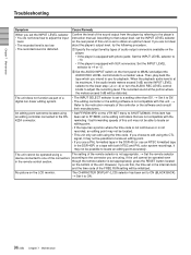
...will be located using the time code. The unit cannot be possible to adjust the input level. • The recorded level is too low. • The recorded sound is equipped with the rewinding / fast-forwarding speeds of this item has been set to ON (BLACK BACK). ...DSR-45 (or use for playback. t Set it may not be possible to obtain an optimum level. t Refer to the player's instruction manual. If you are not clear about the player's output level, try the following procedure. 1 Specify the output level by referring to the instruction manuals of a digital non-linear editing...
...will be located using the time code. The unit cannot be possible to adjust the input level. • The recorded level is too low. • The recorded sound is equipped with the rewinding / fast-forwarding speeds of this item has been set to ON (BLACK BACK). ...DSR-45 (or use for playback. t Set it may not be possible to obtain an optimum level. t Refer to the player's instruction manual. If you are not clear about the player's output level, try the following procedure. 1 Specify the output level by referring to the instruction manuals of a digital non-linear editing...


