

User Manual
Page 54
...6900-29 Daniels Parkway, PMB 330 Fort Myers, Florida 33912 Declaration of Conformity Trade Name: Model: Responsible Party: Address: Telephone Number: SONY PFM-42B1/42B2 Sony Electronics Inc. 680 Kinderkamack Road, Oradell NJ 07649 U.S.A. 201-930-6972 interference to radio or television reception, which the receiver is ... harmful 2 (GB) For customers in accordance with the limits for help. To avoid electrical shock, do not expose the unit to Part 15 of the FCC Rules. This equipment generates, uses, and can be easily accessible. Refer to these numbers whenever you have any...
...6900-29 Daniels Parkway, PMB 330 Fort Myers, Florida 33912 Declaration of Conformity Trade Name: Model: Responsible Party: Address: Telephone Number: SONY PFM-42B1/42B2 Sony Electronics Inc. 680 Kinderkamack Road, Oradell NJ 07649 U.S.A. 201-930-6972 interference to radio or television reception, which the receiver is ... harmful 2 (GB) For customers in accordance with the limits for help. To avoid electrical shock, do not expose the unit to Part 15 of the FCC Rules. This equipment generates, uses, and can be easily accessible. Refer to these numbers whenever you have any...
User Manual
Page 55
Table of Contents Precautions 5 (GB) Features 6 (GB) Location and Function of Parts and Controls ....... 7 (GB) Front / Rear / Right Side 7 (GB) 1 (standby) Switch / Indicator Section 8 (GB) Control Button Section (Rear 8 (GB) Connector Panel 9 (GB) Remote Commander RM-42B ...11 (GB) Caution 13 (GB) Connections 14 (GB) Connecting the AC Power Cord 14 (GB) Attaching the ferrite core (PFM-42B2/42B2E only 14 (GB) Connection Example 15 (GB) Using On-screen Menus 20 (GB) Operating Through Menus 20 (GB) GB Menu Guide 20 (GB...
Table of Contents Precautions 5 (GB) Features 6 (GB) Location and Function of Parts and Controls ....... 7 (GB) Front / Rear / Right Side 7 (GB) 1 (standby) Switch / Indicator Section 8 (GB) Control Button Section (Rear 8 (GB) Connector Panel 9 (GB) Remote Commander RM-42B ...11 (GB) Caution 13 (GB) Connections 14 (GB) Connecting the AC Power Cord 14 (GB) Attaching the ferrite core (PFM-42B2/42B2E only 14 (GB) Connection Example 15 (GB) Using On-screen Menus 20 (GB) Operating Through Menus 20 (GB) GB Menu Guide 20 (GB...

User Manual
Page 57
...and leave a ghosting image behind. As a safety precaution, unplug the unit before operating it any questions about this unit, contact your authorized Sony dealer. 5 (GB) Noise when using the Infrared communication equipment Communication problems may occur if the infrared communication equipment (e.g., infrared cordless headphones or... microphones) is installed on the carton. Do not place the unit on the screen for a long period of time, part of that may burn into the panel, use the infrared communication equipment, move the transmitter and receiver of the way it as at...
...and leave a ghosting image behind. As a safety precaution, unplug the unit before operating it any questions about this unit, contact your authorized Sony dealer. 5 (GB) Noise when using the Infrared communication equipment Communication problems may occur if the infrared communication equipment (e.g., infrared cordless headphones or... microphones) is installed on the carton. Do not place the unit on the screen for a long period of time, part of that may burn into the panel, use the infrared communication equipment, move the transmitter and receiver of the way it as at...

User Manual
Page 59
... AC power cord, the STANDBY indicator lights up in the illustration above are all ventilation holes. Location and Function of Parts and Controls Front / Rear / Right Side Front 1 Location and Function of Parts and Controls 1 1 (standby) switch / indicator section For details on the 1 (standby) switch / indicator section, see "1 (standby) Switch / Indicator Section...
... AC power cord, the STANDBY indicator lights up in the illustration above are all ventilation holes. Location and Function of Parts and Controls Front / Rear / Right Side Front 1 Location and Function of Parts and Controls 1 1 (standby) switch / indicator section For details on the 1 (standby) switch / indicator section, see "1 (standby) Switch / Indicator Section...

User Manual
Page 60
Location and Function of Parts and Controls 1 (standby) Switch / Indicator Section Control Button Section (Rear) 4 3 1 2 2 1 3 1 1 (standby) switch Press to the previous menu level. When the menu appears on the display ...
Location and Function of Parts and Controls 1 (standby) Switch / Indicator Section Control Button Section (Rear) 4 3 1 2 2 1 3 1 1 (standby) switch Press to the previous menu level. When the menu appears on the display ...
User Manual
Page 61
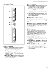
...Connects to the audio output of a computer or a piece of video equipment. For the PFM-42B1E/42B2E, composite video and Y/C input can be input to the audio output of a ...the RGB signal or component (YUV) signal output of a computer or a piece of video equipment. Location and Function of Parts and Controls 2 INPUT2 connectors RGB/YUV (D-sub 15-pin): Connects to the RGB signal or component (YUV) signal output.... AUDIO (Stereo minijack): Inputs an audio signal. For details, contact your authorized Sony dealer. 5 VIDEO connectors The PFM-42B1E/42B2E are not equipped with VIDEO connectors.
...Connects to the audio output of a computer or a piece of video equipment. For the PFM-42B1E/42B2E, composite video and Y/C input can be input to the audio output of a ...the RGB signal or component (YUV) signal output of a computer or a piece of video equipment. Location and Function of Parts and Controls 2 INPUT2 connectors RGB/YUV (D-sub 15-pin): Connects to the RGB signal or component (YUV) signal output.... AUDIO (Stereo minijack): Inputs an audio signal. For details, contact your authorized Sony dealer. 5 VIDEO connectors The PFM-42B1E/42B2E are not equipped with VIDEO connectors.
User Manual
Page 62
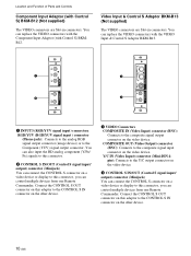
... on this adaptor to the CONTROL S IN connector on the video device. You can control multiple devices from one Remote Commander. Location and Function of Parts and Controls Component Input Adaptor (with the VIDEO Input & Control S Adaptor BKM-B13. You can also input the HD analog component (Y/PB/ PR) signals to...
... on this adaptor to the CONTROL S IN connector on the video device. You can control multiple devices from one Remote Commander. Location and Function of Parts and Controls Component Input Adaptor (with the VIDEO Input & Control S Adaptor BKM-B13. You can also input the HD analog component (Y/PB/ PR) signals to...

User Manual
Page 63
Press again to the Y/ C output connector of the display panel. Location and Function of Parts and Controls Remote Commander RM-42B 1 qs 2 3 qd 4 5 qf 6 Y/C 1 qg VIDEO IN COMPOSITE qh qj 7 qk 8 ql 2 9 w; 0 wa qa 3 4 5 1 VIDEO IN connector Y/C connector (Mini DIN 4 ...
Press again to the Y/ C output connector of the display panel. Location and Function of Parts and Controls Remote Commander RM-42B 1 qs 2 3 qd 4 5 qf 6 Y/C 1 qg VIDEO IN COMPOSITE qh qj 7 qk 8 ql 2 9 w; 0 wa qa 3 4 5 1 VIDEO IN connector Y/C connector (Mini DIN 4 ...

User Manual
Page 64
... page 45 (GB). Installing batteries Insert two size AA (R6) batteries in a menu. qd RGB/YUV button Press to select the format matching that of Parts and Controls 8 H SHIFT button Adjusts the horizontal centering. ql ENTER button Press to make an index number appear on the display panel, press to return...
... page 45 (GB). Installing batteries Insert two size AA (R6) batteries in a menu. qd RGB/YUV button Press to select the format matching that of Parts and Controls 8 H SHIFT button Adjusts the horizontal centering. ql ENTER button Press to make an index number appear on the display panel, press to return...

User Manual
Page 75
...section also flashes. The display turns to the standby mode and the REMOTE ONLY mode is not counted as part of operation. Note The standby mode is cancelled. OK: Normal NG: Unusual When the internal temperature is... eg SERIAL No. When the STANDBY indicator flashes or NG is still shown, contact your authorized Sony dealer. If the ambient temperature is high, the fan speed increases and the fan noise will ...into this case, check that the ventilation holes are not working normally, NG is based on the PFM-42B2E. To cancel the REMOTE ONLY mode, set the number, use the buttons on the display...
...section also flashes. The display turns to the standby mode and the REMOTE ONLY mode is not counted as part of operation. Note The standby mode is cancelled. OK: Normal NG: Unusual When the internal temperature is... eg SERIAL No. When the STANDBY indicator flashes or NG is still shown, contact your authorized Sony dealer. If the ambient temperature is high, the fan speed increases and the fan noise will ...into this case, check that the ventilation holes are not working normally, NG is based on the PFM-42B2E. To cancel the REMOTE ONLY mode, set the number, use the buttons on the display...


