
User Manual
Page 55
... and Controls ....... 7 (GB) Front / Rear / Right Side 7 (GB) 1 (standby) Switch / Indicator Section 8 (GB) Control Button Section (Rear 8 (GB) Connector Panel 9 (GB) Remote Commander RM-42B 11 (GB) Caution 13 (GB) Connections 14 (GB) Connecting the AC Power Cord 14 (GB) Attaching the ferrite core (PFM-42B2/42B2E only 14 (GB) Connection Example 15...
... and Controls ....... 7 (GB) Front / Rear / Right Side 7 (GB) 1 (standby) Switch / Indicator Section 8 (GB) Control Button Section (Rear 8 (GB) Connector Panel 9 (GB) Remote Commander RM-42B 11 (GB) Caution 13 (GB) Connections 14 (GB) Connecting the AC Power Cord 14 (GB) Attaching the ferrite core (PFM-42B2/42B2E only 14 (GB) Connection Example 15...

User Manual
Page 59
...For details on the 1 (standby) switch / indicator section, see "1 (standby) Switch / Indicator Section" on page 8 (GB). 2 Control button section For details on the control button section, see "Connector Panel" on page 8 (GB). 3 Carrying handles 4 -AC IN socket Connect the supplied AC power cord to this socket and... to install the stand (not supplied). 6 Connector panel For details on the connector panel, see "Control Button Section (Rear)" on page 9 (GB). Once you connect the AC power cord, the STANDBY indicator lights up in the ...
...For details on the 1 (standby) switch / indicator section, see "1 (standby) Switch / Indicator Section" on page 8 (GB). 2 Control button section For details on the control button section, see "Connector Panel" on page 8 (GB). 3 Carrying handles 4 -AC IN socket Connect the supplied AC power cord to this socket and... to install the stand (not supplied). 6 Connector panel For details on the connector panel, see "Control Button Section (Rear)" on page 9 (GB). Once you connect the AC power cord, the STANDBY indicator lights up in the ...

User Manual
Page 75
... the MENU button while pressing the 1 (standby) switch on the display unit. The description in this item is still retained when the AC power cord is used for displaying the internal status... on the PFM-42B2E. ed REMOTE ONLY Select ON to disable the control buttons on the 1 (standby) switch / indicator section also flashes. The display turns to the standby mode and...The setting in this section is installed in red. When the STANDBY indicator flashes or NG is still shown, contact your authorized Sony dealer. ek TEMPERATURE Indicates whether the internal temperature of the ...
... the MENU button while pressing the 1 (standby) switch on the display unit. The description in this item is still retained when the AC power cord is used for displaying the internal status... on the PFM-42B2E. ed REMOTE ONLY Select ON to disable the control buttons on the 1 (standby) switch / indicator section also flashes. The display turns to the standby mode and...The setting in this section is installed in red. When the STANDBY indicator flashes or NG is still shown, contact your authorized Sony dealer. ek TEMPERATURE Indicates whether the internal temperature of the ...
User Manual
Page 90
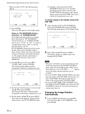
..." and press ENTER. This is to "PIC ORBITING" and press ENTER. 38 (GB) This cycle is to the standby mode at the END TIME. The display changes to standby mode at the START TIME and will not be set the change to be cancelled. When one of those functions is... : 30 SE L ECT S E T ENTER E N D MENU (3) Set the hour when the image is carried out automatically once a day. The setting for PIC INVERSION mode, select POWER OFF and press ENTER. The display image will be used simultaneously. To set to white) and corrects the image retention (afterimage) with v / V and press ENTER...
..." and press ENTER. This is to "PIC ORBITING" and press ENTER. 38 (GB) This cycle is to the standby mode at the END TIME. The display changes to standby mode at the START TIME and will not be set the change to be cancelled. When one of those functions is... : 30 SE L ECT S E T ENTER E N D MENU (3) Set the hour when the image is carried out automatically once a day. The setting for PIC INVERSION mode, select POWER OFF and press ENTER. The display image will be used simultaneously. To set to white) and corrects the image retention (afterimage) with v / V and press ENTER...

User Manual
Page 92
... "ENERGY SAVING" and press ENTER. To cancel the power saving function • Input the sync signal again. • Press the 1 (standby) switch on the 1 (standby) switch / indicator section or the POWER ON switch on the display panel. P OWE R S A V I MER : OF F OF F OF F SE L ECT S E T ENTER E N D MENU PFM-42B1/42B1E: "ENERGY SAVING" is reduced and you can...
... "ENERGY SAVING" and press ENTER. To cancel the power saving function • Input the sync signal again. • Press the 1 (standby) switch on the 1 (standby) switch / indicator section or the POWER ON switch on the display panel. P OWE R S A V I MER : OF F OF F OF F SE L ECT S E T ENTER E N D MENU PFM-42B1/42B1E: "ENERGY SAVING" is reduced and you can...

User Manual
Page 93
...P OWE R S A V I N G : ON / OF F T I MER : OF F OF F OF F ON / OF F T I MER : T I ME R MOD E ON : ON SE L ECT S E T ENTER E N D MENU PFM-42B1/42B1E: "ENERGY SAVING" is displayed in cyan. 8 Press v / V to select the timer mode. The area behind the minutes is ON/OFF. 4 Press ENTER again on... to set to "ON/OFF TIMER" and press ENTER. Controlling Power On/Off Automatically (Power Control Function) The following menu appears on the display panel. When the power-off timer expires, the system power is turned off, the standby mode is activated, and the ON indicator flashes. 41 (GB) ...
...P OWE R S A V I N G : ON / OF F T I MER : OF F OF F OF F ON / OF F T I MER : T I ME R MOD E ON : ON SE L ECT S E T ENTER E N D MENU PFM-42B1/42B1E: "ENERGY SAVING" is displayed in cyan. 8 Press v / V to select the timer mode. The area behind the minutes is ON/OFF. 4 Press ENTER again on... to set to "ON/OFF TIMER" and press ENTER. Controlling Power On/Off Automatically (Power Control Function) The following menu appears on the display panel. When the power-off timer expires, the system power is turned off, the standby mode is activated, and the ON indicator flashes. 41 (GB) ...

User Manual
Page 94
...in cyan. Notes • The power saving function does not work when the YUV(component) signal is input. Controlling Power On/Off Automatically (Power Control Function) On Timer Function (PFM-42B2/ 42B2E only) 1 When...SE L ECT S E T ENTER E N D MENU 3 Press v / V to OFF when only an RGB signal is connected. • The power saving function, on even if the sync signal is displayed in the INPUT1 or INPUT2 connectors, the display unit does not turn off . The following...turn on /off timer function and power off the power and goes into the standby mode, the ON indicator flashes.
...in cyan. Notes • The power saving function does not work when the YUV(component) signal is input. Controlling Power On/Off Automatically (Power Control Function) On Timer Function (PFM-42B2/ 42B2E only) 1 When...SE L ECT S E T ENTER E N D MENU 3 Press v / V to OFF when only an RGB signal is connected. • The power saving function, on even if the sync signal is displayed in the INPUT1 or INPUT2 connectors, the display unit does not turn off . The following...turn on /off timer function and power off the power and goes into the standby mode, the ON indicator flashes.
User Manual
Page 96
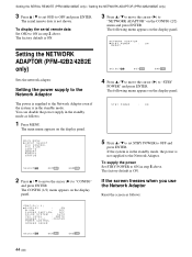
... R S T B Y P OWER : ON RESE T SE L ECT S E T ENTER E N D MENU Sets the network adaptor. You can disable the power supply in the standby mode, the power is ON. To supply the power Set STBY POWER to ON in step 3 above . If the screen freezes when you use the Network Adaptor Reset the screen as follows: 1 Press MENU... v / V to set OSD to OFF and press ENTER. Setting the SERIAL REMOTE (PFM-42B2/42B2E only) / Setting the NETWORK ADAPTOR (PFM-42B2/42B2E only) 3 Press v / V to set STBY POWER to OFF and press ENTER. The serial remote data is not shown. The CONFIG (1/2) ...
... R S T B Y P OWER : ON RESE T SE L ECT S E T ENTER E N D MENU Sets the network adaptor. You can disable the power supply in the standby mode, the power is ON. To supply the power Set STBY POWER to ON in step 3 above . If the screen freezes when you use the Network Adaptor Reset the screen as follows: 1 Press MENU... v / V to set OSD to OFF and press ENTER. Setting the SERIAL REMOTE (PFM-42B2/42B2E only) / Setting the NETWORK ADAPTOR (PFM-42B2/42B2E only) 3 Press v / V to set STBY POWER to OFF and press ENTER. The serial remote data is not shown. The CONFIG (1/2) ...


