
User Manual
Page 55
... and Function of Parts and Controls ....... 7 (GB) Front / Rear / Right Side 7 (GB) 1 (standby) Switch / Indicator Section 8 (GB) Control Button Section (Rear 8 (GB) Connector Panel 9 (GB) Remote Commander RM-42B 11 (GB) Caution 13 (GB) Connections 14 (GB) Connecting the AC Power Cord 14 (GB) Attaching the ferrite core... (PFM-42B2/42B2E only 14 (GB) Connection Example 15 (GB) Using On-screen Menus 20 (GB) Operating Through Menus 20 (GB) GB Menu Guide 20 (GB) ...
... and Function of Parts and Controls ....... 7 (GB) Front / Rear / Right Side 7 (GB) 1 (standby) Switch / Indicator Section 8 (GB) Control Button Section (Rear 8 (GB) Connector Panel 9 (GB) Remote Commander RM-42B 11 (GB) Caution 13 (GB) Connections 14 (GB) Connecting the AC Power Cord 14 (GB) Attaching the ferrite core... (PFM-42B2/42B2E only 14 (GB) Connection Example 15 (GB) Using On-screen Menus 20 (GB) Operating Through Menus 20 (GB) GB Menu Guide 20 (GB) ...

User Manual
Page 56
... (GB) Power Saving Function 40 (GB) On/Off Timer Function 40 (GB) On Timer Function (PFM-42B2/42B2E only) ....... 42 (GB) Off Timer Function (PFM-42B2/42B2E only) ...... 42 (GB) Setting the SERIAL REMOTE (PFM-42B2/42B2E only 43 (GB) Setting the baud rate 43 (GB) OSD Function 43 (GB) Setting... the NETWORK ADAPTOR (PFM-42B2/42B2E only 44 (GB) Setting the power supply to the Network Adaptor 44...
... (GB) Power Saving Function 40 (GB) On/Off Timer Function 40 (GB) On Timer Function (PFM-42B2/42B2E only) ....... 42 (GB) Off Timer Function (PFM-42B2/42B2E only) ...... 42 (GB) Setting the SERIAL REMOTE (PFM-42B2/42B2E only 43 (GB) Setting the baud rate 43 (GB) OSD Function 43 (GB) Setting... the NETWORK ADAPTOR (PFM-42B2/42B2E only 44 (GB) Setting the power supply to the Network Adaptor 44...

User Manual
Page 57
...a few dark or bright pixels. When cleaning, use the screen function provided, displaying it any questions about this unit, contact your authorized Sony dealer. 5 (GB) On repacking Do not throw away the carton and packing materials. It may block the ventilation holes. • ...place the unit on the back of the panel, and leave a ghosting image behind. Please use strong solvents such as malfunction of the Remote Commander, noisy picture, noisy sound, may occur if the infrared communication equipment (e.g., infrared cordless headphones or microphones) is located on surfaces ...
...a few dark or bright pixels. When cleaning, use the screen function provided, displaying it any questions about this unit, contact your authorized Sony dealer. 5 (GB) On repacking Do not throw away the carton and packing materials. It may block the ventilation holes. • ...place the unit on the back of the panel, and leave a ghosting image behind. Please use strong solvents such as malfunction of the Remote Commander, noisy picture, noisy sound, may occur if the infrared communication equipment (e.g., infrared cordless headphones or microphones) is located on surfaces ...

User Manual
Page 58
...8226; Remote (RS-232C) connector (D-sub 9-pin) • Accepts infrared Sony Remote Commanders using SIRCS code. • Vertical setup • Closed caption decoder • Screen saver to 1024 dots × 1024 lines. Other features • Three sets of formats - Improved image quality The PFM-42B1/42B2/... power cord for a finely-detailed HDTV or PC image. Using a unique algorithm, the display processes signals in scan converter. PFM-42B1/42B1E United States, Canada Continental Europe United Kingdom, Ireland, Australia, New Zealand Plug type VM0233 COX-07 636 -a) Female end...
...8226; Remote (RS-232C) connector (D-sub 9-pin) • Accepts infrared Sony Remote Commanders using SIRCS code. • Vertical setup • Closed caption decoder • Screen saver to 1024 dots × 1024 lines. Other features • Three sets of formats - Improved image quality The PFM-42B1/42B2/... power cord for a finely-detailed HDTV or PC image. Using a unique algorithm, the display processes signals in scan converter. PFM-42B1/42B1E United States, Canada Continental Europe United Kingdom, Ireland, Australia, New Zealand Plug type VM0233 COX-07 636 -a) Female end...

User Manual
Page 60
... make the menu appear. Location and Function of Parts and Controls 1 (standby) Switch / Indicator Section Control Button Section (Rear) 4 3 1 2 2 1 3 1 1 (standby) switch Press to turn on . 4 Remote control detector Receives the signal from the Remote Commander. 1 MENU button Press to select the desired item from the menu displayed. 8 (GB)
... make the menu appear. Location and Function of Parts and Controls 1 (standby) Switch / Indicator Section Control Button Section (Rear) 4 3 1 2 2 1 3 1 1 (standby) switch Press to turn on . 4 Remote control detector Receives the signal from the Remote Commander. 1 MENU button Press to select the desired item from the menu displayed. 8 (GB)
User Manual
Page 61
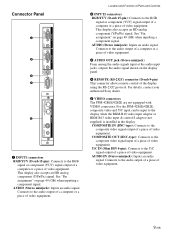
..."Pin assignment" on page 49 (GB) when inputting a component signal. For details, contact your authorized Sony dealer. 5 VIDEO connectors The PFM-42B1E/42B2E are not equipped with VIDEO connectors. For the PFM-42B1E/42B2E, composite video and Y/C input can be input to the audio output of a computer or ...the audio signals input at the audio input jacks, outputs the audio signal shown on the display panel. 4 REMOTE (RS-232C) connector (D-sub 9-pin) This connector allows remote control of the display using the RS-232C protocol. AUDIO (Stereo minijack): Inputs an audio signal. Connects to ...
..."Pin assignment" on page 49 (GB) when inputting a component signal. For details, contact your authorized Sony dealer. 5 VIDEO connectors The PFM-42B1E/42B2E are not equipped with VIDEO connectors. For the PFM-42B1E/42B2E, composite video and Y/C input can be input to the audio output of a computer or ...the audio signals input at the audio input jacks, outputs the audio signal shown on the display panel. 4 REMOTE (RS-232C) connector (D-sub 9-pin) This connector allows remote control of the display using the RS-232C protocol. AUDIO (Stereo minijack): Inputs an audio signal. Connects to ...
User Manual
Page 62
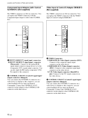
...the VIDEO connectors with the Component Input Adaptor (with the VIDEO Input & Control S Adaptor BKM-B13. You can control multiple devices from one Remote Commander. Y/C IN (Video Input) connector (Mini-DIN 4pin): Connects to the Y/C output connector on the video device. 2 CONTROL S IN/...OUT (Control S signal input/ output) connector (Minijack) You can control multiple devices from one Remote Commander. Connect the CONTROL S OUT connector on this adaptor to the CONTROL S IN connector on the other device. 1 VIDEO Connectors COMPOSITE IN ...
...the VIDEO connectors with the Component Input Adaptor (with the VIDEO Input & Control S Adaptor BKM-B13. You can control multiple devices from one Remote Commander. Y/C IN (Video Input) connector (Mini-DIN 4pin): Connects to the Y/C output connector on the video device. 2 CONTROL S IN/...OUT (Control S signal input/ output) connector (Minijack) You can control multiple devices from one Remote Commander. Connect the CONTROL S OUT connector on this adaptor to the CONTROL S IN connector on the other device. 1 VIDEO Connectors COMPOSITE IN ...

User Manual
Page 63
... display. 2 DISPLAY button Displays the input signal information and the time at the top of an image device. Location and Function of Parts and Controls Remote Commander RM-42B 1 qs 2 3 qd 4 5 qf 6 Y/C 1 qg VIDEO IN COMPOSITE qh qj 7 qk 8 ql 2 9 w; 0 wa qa 3 4 5 1 VIDEO IN connector Y/C connector (Mini DIN 4 pin): Connect to...
... display. 2 DISPLAY button Displays the input signal information and the time at the top of an image device. Location and Function of Parts and Controls Remote Commander RM-42B 1 qs 2 3 qd 4 5 qf 6 Y/C 1 qg VIDEO IN COMPOSITE qh qj 7 qk 8 ql 2 9 w; 0 wa qa 3 4 5 1 VIDEO IN connector Y/C connector (Mini DIN 4 pin): Connect to...

User Manual
Page 64
... negative BRIGHT +/- button Adjusts the contrast. Be sure to enter the index number. For details about the index number, see "Operating a Specific Display With the Remote Commander" on the screen. qs STANDBY button Press to turn the display to the previous menu level. Then enter the index number of the display...
... negative BRIGHT +/- button Adjusts the contrast. Be sure to enter the index number. For details about the index number, see "Operating a Specific Display With the Remote Commander" on the screen. qs STANDBY button Press to turn the display to the previous menu level. Then enter the index number of the display...

User Manual
Page 67
...; Use connecting cables suitable for the equipment to any of the cable closer to the PFM-42B2/42B2E, closing it firmly until your hear it out by grasping the plug. AUDIO (INPUT1) AUDIO (INPUT2) AUDIO OUT REMOTE Y/C IN (VIDEO) AUDIO IN (VIDEO) 1 Attach the ferrite core (black) to the end of the...
...; Use connecting cables suitable for the equipment to any of the cable closer to the PFM-42B2/42B2E, closing it firmly until your hear it out by grasping the plug. AUDIO (INPUT1) AUDIO (INPUT2) AUDIO OUT REMOTE Y/C IN (VIDEO) AUDIO IN (VIDEO) 1 Attach the ferrite core (black) to the end of the...
User Manual
Page 72
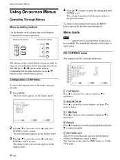
... the language used for the selected item appears on the display panel. 4 Press v / V to adjust or select the setting and press ENTER to select a menu. Remote Commander Control button section The buttons on the display panel. 3 Press v / V to move the cursor (B) and press ENTER to set. MA I N MENU I NPUT SELECT P I C CONTROL... Operating Through Menus Menu operating buttons Use the buttons on the control button section. To return to the previous menu. The SELECT +M/-m button on the Remote Commander has the same functions as the v / V buttons on the display unit or the...
... the language used for the selected item appears on the display panel. 4 Press v / V to adjust or select the setting and press ENTER to select a menu. Remote Commander Control button section The buttons on the display panel. 3 Press v / V to move the cursor (B) and press ENTER to set. MA I N MENU I NPUT SELECT P I C CONTROL... Operating Through Menus Menu operating buttons Use the buttons on the control button section. To return to the previous menu. The SELECT +M/-m button on the Remote Commander has the same functions as the v / V buttons on the display unit or the...
User Manual
Page 73
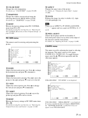
... wd wf SE L ECT S E T ENTER E N D MENU PFM-42B1/42B1E: "YUV LEVEL" is used for resizing and positioning the picture. 9 P I C S I A L R EMO T E N E TWO R K A D A P T O R wk SE L ECT S E T ENTER E N D MENU PFM-42B1/42B1E: "SERIAL REMOTE" is added but it . 6 COLOR TEMP Changes the color temperature. ...qd RESET Restores the factory settings in the PFM-42B1/42B1E. 21 (GB) PIC SIZE menu This menu is not displayed. For details...
... wd wf SE L ECT S E T ENTER E N D MENU PFM-42B1/42B1E: "YUV LEVEL" is used for resizing and positioning the picture. 9 P I C S I A L R EMO T E N E TWO R K A D A P T O R wk SE L ECT S E T ENTER E N D MENU PFM-42B1/42B1E: "SERIAL REMOTE" is added but it . 6 COLOR TEMP Changes the color temperature. ...qd RESET Restores the factory settings in the PFM-42B1/42B1E. 21 (GB) PIC SIZE menu This menu is not displayed. For details...

User Manual
Page 74
... Enables a screen saver to reduce afterimage or ghosting. For details, see "Selecting the On-screen Language" on page 34 (GB). wj SERIAL REMOTE (PFM-42B2/42B2E only) Setting the Serial Remote. MEMORY menu This menu is used for resizing the picture. wl M E M O R Y LOAD e; SAVE SE L ECT S E T ENTER E N D MENU For details, see "Displaying closed...
... Enables a screen saver to reduce afterimage or ghosting. For details, see "Selecting the On-screen Language" on page 34 (GB). wj SERIAL REMOTE (PFM-42B2/42B2E only) Setting the Serial Remote. MEMORY menu This menu is used for resizing the picture. wl M E M O R Y LOAD e; SAVE SE L ECT S E T ENTER E N D MENU For details, see "Displaying closed...

User Manual
Page 75
... is high, the fan speed increases and the fan noise will be controlled with the Remote Commander. Notes • When the "FAN NG" message appears, contact your authorized Sony dealer. If the ambient temperature is disconnected or when you turn the display on/off...(standby) switch / indicator section also flashes. TV: The Sony display's or the TV's commander PJ: The Sony projector's commander OFF: Disables the remote control. STATUS menu This menu is based on the PFM-42B2E. es REMOTE MODE Selects the Remote Commander mode. Indicates the serial number. el FAN Cooling fans ...
... is high, the fan speed increases and the fan noise will be controlled with the Remote Commander. Notes • When the "FAN NG" message appears, contact your authorized Sony dealer. If the ambient temperature is disconnected or when you turn the display on/off...(standby) switch / indicator section also flashes. TV: The Sony display's or the TV's commander PJ: The Sony projector's commander OFF: Disables the remote control. STATUS menu This menu is based on the PFM-42B2E. es REMOTE MODE Selects the Remote Commander mode. Indicates the serial number. el FAN Cooling fans ...
User Manual
Page 76
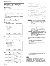
...signal input from the INPUT2 connectors when the input signal is an RGB signal. 24 (GB) You can also switch the input signal using the Remote Commander. The currently selected input signal and INPUT SELECT menu appear on the display panel. Color system or horizontal/vertical frequency Signal type PAL V .... INPUT1 YUV: Selects the audio and video signal input from the COMPOSITE IN connector and AUDIO IN jack among the VIDEO connectors. (For the PFM-42B1E/42B2E, VIDEO COMPOSITE and VIDEO Y/C only appear when the BKM-B10 video input adaptor or BKM-B13 video input & control S adaptor (not...
...signal input from the INPUT2 connectors when the input signal is an RGB signal. 24 (GB) You can also switch the input signal using the Remote Commander. The currently selected input signal and INPUT SELECT menu appear on the display panel. Color system or horizontal/vertical frequency Signal type PAL V .... INPUT1 YUV: Selects the audio and video signal input from the COMPOSITE IN connector and AUDIO IN jack among the VIDEO connectors. (For the PFM-42B1E/42B2E, VIDEO COMPOSITE and VIDEO Y/C only appear when the BKM-B10 video input adaptor or BKM-B13 video input & control S adaptor (not...
User Manual
Page 77
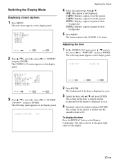
... the display panel. Adjusting the time 1 In the CONFIG (2/2) menu, press v / V to move the cursor (B) to the CONFIG (1/2) menu. The following menu appears on the Remote Commander. Watching the Picture 4 Select the caption type with v / V and press ENTER. T I ME SE T : 00 : 00 : 00 CONF I G ( 1 / 2 ) D I ON : OF F SE L ECT S E T ENTER E N D MENU 2 Press...
... the display panel. Adjusting the time 1 In the CONFIG (2/2) menu, press v / V to move the cursor (B) to the CONFIG (1/2) menu. The following menu appears on the Remote Commander. Watching the Picture 4 Select the caption type with v / V and press ENTER. T I ME SE T : 00 : 00 : 00 CONF I G ( 1 / 2 ) D I ON : OF F SE L ECT S E T ENTER E N D MENU 2 Press...

User Manual
Page 78
... : 30 : 40 26 (GB) The display lasts until you press the DISPLAY button again to "DISPLAY" and press ENTER. The following menu appears on the Remote Commander, regardless of the above . Note You can display the input signal information and the time anytime by pressing the DISPLAY button on the display...
... : 30 : 40 26 (GB) The display lasts until you press the DISPLAY button again to "DISPLAY" and press ENTER. The following menu appears on the Remote Commander, regardless of the above . Note You can display the input signal information and the time anytime by pressing the DISPLAY button on the display...
User Manual
Page 79
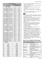
... / 59.9Hz (e.g.) The selected input signal is computer RGB. 480 / 60I (e.g.) The selected input signal is too light after inputting the DVD signal in the PFM-42B1/42B1E, adjust the color in the "CHROMA" setting in item No. 29, set H SIZE, H SHIFT, V SIZE and V SHIFT to the standard (00) and set ...to component video. Actual on the RM-42B Remote Commander to make the necessary adjustments. • When inputting a DTV signal (No.7 to No.14), input it will display at the resolution shown in the...
... / 59.9Hz (e.g.) The selected input signal is computer RGB. 480 / 60I (e.g.) The selected input signal is too light after inputting the DVD signal in the PFM-42B1/42B1E, adjust the color in the "CHROMA" setting in item No. 29, set H SIZE, H SHIFT, V SIZE and V SHIFT to the standard (00) and set ...to component video. Actual on the RM-42B Remote Commander to make the necessary adjustments. • When inputting a DTV signal (No.7 to No.14), input it will display at the resolution shown in the...

User Manual
Page 92
... move the cursor (B) to "POWER CONTROL" and press ENTER. ENERGY SAV I MER : OF F OF F OF F SE L ECT S E T ENTER E N D MENU PFM-42B1/42B1E: "ENERGY SAVING" is no input signal. The ON indicator flashes when the unit is reduced and you can view the display unit while saving...; Press the 1 (standby) switch on the 1 (standby) switch / indicator section or the POWER ON switch on the display panel. The following menu appears on the Remote Commander. P OWE R S A V I MER : OF F OF F OF F SE L ECT S E T ENTER E N D MENU 3 Press v / V to move the cursor (B) to "POWER CONTROL" and...
... move the cursor (B) to "POWER CONTROL" and press ENTER. ENERGY SAV I MER : OF F OF F OF F SE L ECT S E T ENTER E N D MENU PFM-42B1/42B1E: "ENERGY SAVING" is no input signal. The ON indicator flashes when the unit is reduced and you can view the display unit while saving...; Press the 1 (standby) switch on the 1 (standby) switch / indicator section or the POWER ON switch on the display panel. The following menu appears on the Remote Commander. P OWE R S A V I MER : OF F OF F OF F SE L ECT S E T ENTER E N D MENU 3 Press v / V to move the cursor (B) to "POWER CONTROL" and...
User Manual
Page 95
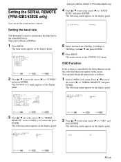
... R EMO T E STATUS SE L ECT S E T ENTER E N D MENU 2 Press v / V to move the cursor (B) to "BAUD RATE" and press ENTER. Setting the SERIAL REMOTE (PFM-42B2/42B2E only) 4 Press v / V to move the cursor (B) to "CONFIG" and press ENTER. The factory default is used to synchronize the baud rate to the... The following menu appears on the display panel. Setting the SERIAL REMOTE (PFM-42B2/42B2E only) You can hide the serial remote data as follows: 1 In the CONFIG (2/2) menu, Press v / V to move the cursor (B) to "SERIAL REMOTE" and press ENTER. MA I N MENU I NPUT SELECT ...
... R EMO T E STATUS SE L ECT S E T ENTER E N D MENU 2 Press v / V to move the cursor (B) to "BAUD RATE" and press ENTER. Setting the SERIAL REMOTE (PFM-42B2/42B2E only) 4 Press v / V to move the cursor (B) to "CONFIG" and press ENTER. The factory default is used to synchronize the baud rate to the... The following menu appears on the display panel. Setting the SERIAL REMOTE (PFM-42B2/42B2E only) You can hide the serial remote data as follows: 1 In the CONFIG (2/2) menu, Press v / V to move the cursor (B) to "SERIAL REMOTE" and press ENTER. MA I N MENU I NPUT SELECT ...


