Operating Instructions
Page 30
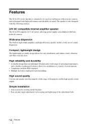
... intended to be used in combination with security cameras, and is also designed with the following features. 24V AC compatible internal amplifier speaker The SCA-S30 supports 24 V AC power, allowing power supply consolidation with the IP66 standard. • Multiple fail-safes employed to prevent falling. High ..., vibration, and other external stress. Compact, lightweight design The lightweight yet sturdy design allows for installation in mind. The speaker is designed with high performance and durability in a variety of environments. • Compliance with Sony network cameras.
... intended to be used in combination with security cameras, and is also designed with the following features. 24V AC compatible internal amplifier speaker The SCA-S30 supports 24 V AC power, allowing power supply consolidation with the IP66 standard. • Multiple fail-safes employed to prevent falling. High ..., vibration, and other external stress. Compact, lightweight design The lightweight yet sturdy design allows for installation in mind. The speaker is designed with high performance and durability in a variety of environments. • Compliance with Sony network cameras.
Operating Instructions
Page 31
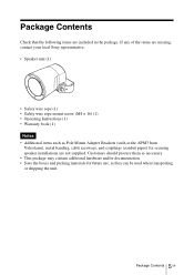
Package Contents Check that the following items are not supplied. If any of the items are missing, contact your local Sony representative. • Speaker unit (1) • Safety wire rope (1) • Safety wire rope mount screw (M4 × 16) (1) • Operating Instructions (1) • Warranty book (1) Notes • Additional items such .... • Save the boxes and packing materials for future use, as the APM3 from Videolarm), metal banding, cable raceways, and couplings (conduit pipes) for securing speaker installations are included in the package.
Package Contents Check that the following items are not supplied. If any of the items are missing, contact your local Sony representative. • Speaker unit (1) • Safety wire rope (1) • Safety wire rope mount screw (M4 × 16) (1) • Operating Instructions (1) • Warranty book (1) Notes • Additional items such .... • Save the boxes and packing materials for future use, as the APM3 from Videolarm), metal banding, cable raceways, and couplings (conduit pipes) for securing speaker installations are included in the package.
Operating Instructions
Page 32
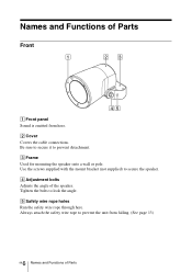
... bracket (not supplied) to prevent the unit from here. D Adjustment bolts Adjusts the angle of Parts Always attach the safety wire rope to secure the speaker. Names and Functions of Parts Front 1 23 45 A Front panel Sound is emitted from falling. (See page 13) 6 GB Names and Functions of the...
... bracket (not supplied) to prevent the unit from here. D Adjustment bolts Adjusts the angle of Parts Always attach the safety wire rope to secure the speaker. Names and Functions of Parts Front 1 23 45 A Front panel Sound is emitted from falling. (See page 13) 6 GB Names and Functions of the...
Operating Instructions
Page 35
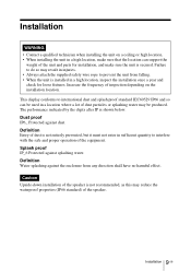
... proof standard IEC60529 IP66 and so can support the weight of the equipment. Increase the frequency of the speaker. 9 Installation GB Splash proof IP_6 Protected against dust. Caution Upside-down installation of the speaker is shown below. This display conforms to interfere with the safe and proper operation of the unit and...
... proof standard IEC60529 IP66 and so can support the weight of the equipment. Increase the frequency of the speaker. 9 Installation GB Splash proof IP_6 Protected against dust. Caution Upside-down installation of the speaker is shown below. This display conforms to interfere with the safe and proper operation of the unit and...
Operating Instructions
Page 36
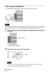
... secure the Pole Mount Adapter Bracket onto the pole or column. Metal banding Pole Mount Adapter Bracket 2 Remove the cover at the rear of the speaker. Cover Notes • The cover screws are not supplied. Note Pole Mount Adapter Brackets, metal banding, cable raceways, couplings, nuts, audio signal cables, and power...
... secure the Pole Mount Adapter Bracket onto the pole or column. Metal banding Pole Mount Adapter Bracket 2 Remove the cover at the rear of the speaker. Cover Notes • The cover screws are not supplied. Note Pole Mount Adapter Brackets, metal banding, cable raceways, couplings, nuts, audio signal cables, and power...

Operating Instructions
Page 37
Coupling Cable raceway 4 Insert the coupling through the raceway, and attach the coupling. Nut 5 Use the nuts and bolts supplied with the coupling. 3 Run the audio signal cable and power cables through the connection port on the speaker, and secure it with the nut supplied with the Pole Mount Adapter Bracket to secure the speaker to the bracket. 11 Installation GB
Coupling Cable raceway 4 Insert the coupling through the raceway, and attach the coupling. Nut 5 Use the nuts and bolts supplied with the coupling. 3 Run the audio signal cable and power cables through the connection port on the speaker, and secure it with the nut supplied with the Pole Mount Adapter Bracket to secure the speaker to the bracket. 11 Installation GB
Operating Instructions
Page 38
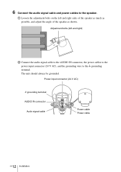
A Loosen the adjustment bolts on the left and right) B Connect the audio signal cable to the AUDIO IN connector, the power cables to the power input connector (24 V AC), and the grounding wire to the speaker. Power input connector (24 V AC) U grounding terminal AUDIO IN connector Audio signal cable Power cable Power cable 12 GB Installation Adjustment bolts (left and right sides of the speaker as much as possible, and adjust the angle of the speaker as shown. The unit should always be grounded. 6 Connect the audio signal cable and power cables to the U grounding terminal.
A Loosen the adjustment bolts on the left and right) B Connect the audio signal cable to the AUDIO IN connector, the power cables to the power input connector (24 V AC), and the grounding wire to the speaker. Power input connector (24 V AC) U grounding terminal AUDIO IN connector Audio signal cable Power cable Power cable 12 GB Installation Adjustment bolts (left and right sides of the speaker as much as possible, and adjust the angle of the speaker as shown. The unit should always be grounded. 6 Connect the audio signal cable and power cables to the U grounding terminal.
Operating Instructions
Page 39
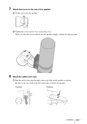
Be sure to use one of the speaker. B Tighten the cover screws (3) to secure the speaker. Example Example 13 Installation GB Make sure that cover to the rear of the four wire rope holes to secure the cover. A Run the safety wire rope through a wire rope hole on the speaker as shown. A Fit the cover onto the speaker. 7 Attach that the cover is fitted onto the speaker snugly, without leaving any gaps. 8 Attach the safety wire rope.
Be sure to use one of the speaker. B Tighten the cover screws (3) to secure the speaker. Example Example 13 Installation GB Make sure that cover to the rear of the four wire rope holes to secure the cover. A Run the safety wire rope through a wire rope hole on the speaker as shown. A Fit the cover onto the speaker. 7 Attach that the cover is fitted onto the speaker snugly, without leaving any gaps. 8 Attach the safety wire rope.
Operating Instructions
Page 40
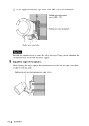
Safety wire rope mount screw (M4 × 16) Safety wire rope (supplied) Safety wire rope holes Caution Use only the supplied screw to secure the rope. Using a screw other than the one supplied may not provide sufficient support. 9 Adjust the angle of the speaker to lock. 14 GB Installation Tighten the left and right sides of the speaker. After adjusting the angle, tighten the adjustment bolts on the left and right adjustment bolts to lock the angle. B Use the supplied safety wire rope mount screw (M4 × 16) to secure the safety wire rope.
Safety wire rope mount screw (M4 × 16) Safety wire rope (supplied) Safety wire rope holes Caution Use only the supplied screw to secure the rope. Using a screw other than the one supplied may not provide sufficient support. 9 Adjust the angle of the speaker to lock. 14 GB Installation Tighten the left and right sides of the speaker. After adjusting the angle, tighten the adjustment bolts on the left and right adjustment bolts to lock the angle. B Use the supplied safety wire rope mount screw (M4 × 16) to secure the safety wire rope.

Operating Instructions
Page 41
Coupling Cable raceway 15 Installation GB Customers should procure them as necessary. 1 Remove the cover at the rear of the speaker. Cover Notes • The cover screws are not supplied. Wall Installation Note Cable raceways, couplings, nuts, audio signal cables, and power cables are screwed tightly to the speaker and may be difficult to remove. • The cover is attached to the speaker with a coiled cord. 2 Run the audio signal cable and power cables through the raceway, and attach the coupling.
Coupling Cable raceway 15 Installation GB Customers should procure them as necessary. 1 Remove the cover at the rear of the speaker. Cover Notes • The cover screws are not supplied. Wall Installation Note Cable raceways, couplings, nuts, audio signal cables, and power cables are screwed tightly to the speaker and may be difficult to remove. • The cover is attached to the speaker with a coiled cord. 2 Run the audio signal cable and power cables through the raceway, and attach the coupling.
Operating Instructions
Page 42
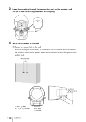
Mount bolts 2 - 12 × 11 mm (2 - 1/2 × 7/16 inches) 50.8 mm (2 inches) 16 GB Installation 58.4 mm (23/8 inches) Nut 4 Secure the speaker to the wall. A Secure two mount bolts to the wall. When installing the mount bolts, be sure to take into account the distance between the speaker cover and the wall. 3 Insert the coupling through the connection port on the speaker frame and the distance between the bolt hole centers on the speaker, and secure it with the nut supplied with the coupling.
Mount bolts 2 - 12 × 11 mm (2 - 1/2 × 7/16 inches) 50.8 mm (2 inches) 16 GB Installation 58.4 mm (23/8 inches) Nut 4 Secure the speaker to the wall. A Secure two mount bolts to the wall. When installing the mount bolts, be sure to take into account the distance between the speaker cover and the wall. 3 Insert the coupling through the connection port on the speaker frame and the distance between the bolt hole centers on the speaker, and secure it with the nut supplied with the coupling.

Operating Instructions
Page 43
The unit should always be grounded. Adjustment bolts (left and right sides of the speaker as much as possible, and adjust the angle of the speaker as shown. A Loosen the adjustment bolts on the left and right) B Connect the audio signal cable to the AUDIO IN connector, the power cables... to the power input connector (24 V AC), and the grounding wire to the speaker. Power input connector (24 V AC) U grounding terminal AUDIO IN connector Audio signal cable Power cable Power cable 17 Installation GB B Use washers and ...
The unit should always be grounded. Adjustment bolts (left and right sides of the speaker as much as possible, and adjust the angle of the speaker as shown. A Loosen the adjustment bolts on the left and right) B Connect the audio signal cable to the AUDIO IN connector, the power cables... to the power input connector (24 V AC), and the grounding wire to the speaker. Power input connector (24 V AC) U grounding terminal AUDIO IN connector Audio signal cable Power cable Power cable 17 Installation GB B Use washers and ...
Operating Instructions
Page 44
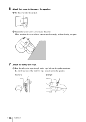
A Run the safety wire rope through a wire rope hole on the speaker as shown. 6 Attach that the cover is fitted onto the speaker snugly, without leaving any gaps. 7 Attach the safety wire rope. Make sure that cover to secure the cover. B Tighten the cover screws (3) to the rear of the four wire rope holes to secure the speaker. A Fit the cover onto the speaker. Be sure to use one of the speaker. Example Example 18 GB Installation
A Run the safety wire rope through a wire rope hole on the speaker as shown. 6 Attach that the cover is fitted onto the speaker snugly, without leaving any gaps. 7 Attach the safety wire rope. Make sure that cover to secure the cover. B Tighten the cover screws (3) to the rear of the four wire rope holes to secure the speaker. A Fit the cover onto the speaker. Be sure to use one of the speaker. Example Example 18 GB Installation

Operating Instructions
Page 45
B Use the supplied safety wire rope mount screw (M4 × 16) to secure the safety wire rope. Tighten the left and right sides of the speaker. After adjusting the angle, tighten the adjustment bolts on the left and right adjustment bolts to lock the angle. Safety wire rope mount screw (M4 × 16) Safety wire rope (supplied) Safety wire rope holes Caution Use only the supplied screw to secure the rope. Using a screw other than the one supplied may not provide sufficient support. 8 Adjust the angle of the speaker to lock. 19 Installation GB
B Use the supplied safety wire rope mount screw (M4 × 16) to secure the safety wire rope. Tighten the left and right sides of the speaker. After adjusting the angle, tighten the adjustment bolts on the left and right adjustment bolts to lock the angle. Safety wire rope mount screw (M4 × 16) Safety wire rope (supplied) Safety wire rope holes Caution Use only the supplied screw to secure the rope. Using a screw other than the one supplied may not provide sufficient support. 8 Adjust the angle of the speaker to lock. 19 Installation GB

Operating Instructions
Page 47
... TV transmitters creating a strong magnetic field Protect from shocks. Maintenance For cleaning, lightly wipe the cabinet and panels with a dry cloth afterwards. Major Specifications Speaker Category Active speaker Frequency response 100 Hz to 15,000 Hz (at 5 W output) Maximum output level 35 W or more (at 24 V AC, 1 kHz input) Input impedance 10...
... TV transmitters creating a strong magnetic field Protect from shocks. Maintenance For cleaning, lightly wipe the cabinet and panels with a dry cloth afterwards. Major Specifications Speaker Category Active speaker Frequency response 100 Hz to 15,000 Hz (at 5 W output) Maximum output level 35 W or more (at 24 V AC, 1 kHz input) Input impedance 10...


