Operating Instructions
Page 36
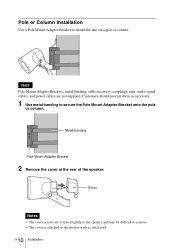
... Notes • The cover screws are not supplied. Note Pole Mount Adapter Brackets, metal banding, cable raceways, couplings, nuts, audio signal cables, and power cables are screwed tightly to the speaker and may be difficult to remove. • The cover is attached to secure the Pole Mount Adapter Bracket onto the pole...
... Notes • The cover screws are not supplied. Note Pole Mount Adapter Brackets, metal banding, cable raceways, couplings, nuts, audio signal cables, and power cables are screwed tightly to the speaker and may be difficult to remove. • The cover is attached to secure the Pole Mount Adapter Bracket onto the pole...

Operating Instructions
Page 37
3 Run the audio signal cable and power cables through the connection port on the speaker, and secure it with the nut supplied with the Pole Mount Adapter Bracket to secure the speaker to the bracket. 11 Installation GB Nut 5 Use the nuts and bolts supplied with the coupling. Coupling Cable raceway 4 Insert the coupling through the raceway, and attach the coupling.
3 Run the audio signal cable and power cables through the connection port on the speaker, and secure it with the nut supplied with the Pole Mount Adapter Bracket to secure the speaker to the bracket. 11 Installation GB Nut 5 Use the nuts and bolts supplied with the coupling. Coupling Cable raceway 4 Insert the coupling through the raceway, and attach the coupling.
Operating Instructions
Page 38
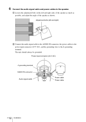
The unit should always be grounded. Power input connector (24 V AC) U grounding terminal AUDIO IN connector Audio signal cable Power cable Power cable 12 GB Installation A Loosen the adjustment bolts on the left and right) B Connect the audio signal cable to the AUDIO IN connector, the power cables to the power input connector (24 V AC), and the grounding wire to the speaker. Adjustment bolts (left and right sides of the speaker as much as possible, and adjust the angle of the speaker as shown. 6 Connect the audio signal cable and power cables to the U grounding terminal.
The unit should always be grounded. Power input connector (24 V AC) U grounding terminal AUDIO IN connector Audio signal cable Power cable Power cable 12 GB Installation A Loosen the adjustment bolts on the left and right) B Connect the audio signal cable to the AUDIO IN connector, the power cables to the power input connector (24 V AC), and the grounding wire to the speaker. Adjustment bolts (left and right sides of the speaker as much as possible, and adjust the angle of the speaker as shown. 6 Connect the audio signal cable and power cables to the U grounding terminal.

Operating Instructions
Page 41
Coupling Cable raceway 15 Installation GB Wall Installation Note Cable raceways, couplings, nuts, audio signal cables, and power cables are screwed tightly to the speaker and may be difficult to remove. • The cover is attached to the speaker with a coiled cord. 2 Run the audio signal cable and power cables through the raceway, and attach the coupling. Customers should procure them as necessary. 1 Remove the cover at the rear of the speaker. Cover Notes • The cover screws are not supplied.
Coupling Cable raceway 15 Installation GB Wall Installation Note Cable raceways, couplings, nuts, audio signal cables, and power cables are screwed tightly to the speaker and may be difficult to remove. • The cover is attached to the speaker with a coiled cord. 2 Run the audio signal cable and power cables through the raceway, and attach the coupling. Customers should procure them as necessary. 1 Remove the cover at the rear of the speaker. Cover Notes • The cover screws are not supplied.

Operating Instructions
Page 43
... much as possible, and adjust the angle of the speaker as shown. B Use washers and nuts to secure the speaker. 5 Connect the audio signal cable and power cables to the U grounding terminal. Power input connector (24 V AC) U grounding terminal AUDIO IN connector Audio signal cable Power cable Power cable 17 Installation GB The unit should...
... much as possible, and adjust the angle of the speaker as shown. B Use washers and nuts to secure the speaker. 5 Connect the audio signal cable and power cables to the U grounding terminal. Power input connector (24 V AC) U grounding terminal AUDIO IN connector Audio signal cable Power cable Power cable 17 Installation GB The unit should...

Operating Instructions
Page 47
... strong magnetic fields • Locations in the vicinity of radio or TV transmitters creating a strong magnetic field Protect from shocks. Major Specifications Speaker Category Active speaker Frequency response 100 Hz to 15,000 Hz (at 5 W output) Maximum output level 35 W or more (at 24 V AC,... 1 kHz input) Input impedance 10 kΩ or more Distortion factor 1% or less (at 24 V AC, 30 W output) S/N ratio 80 dB or more (IEC179 A-weighted, 1 kHz, 30 W) Input connectors AUDIO...
... strong magnetic fields • Locations in the vicinity of radio or TV transmitters creating a strong magnetic field Protect from shocks. Major Specifications Speaker Category Active speaker Frequency response 100 Hz to 15,000 Hz (at 5 W output) Maximum output level 35 W or more (at 24 V AC,... 1 kHz input) Input impedance 10 kΩ or more Distortion factor 1% or less (at 24 V AC, 30 W output) S/N ratio 80 dB or more (IEC179 A-weighted, 1 kHz, 30 W) Input connectors AUDIO...


