
Operating Instructions
Page 5
... 53 Information Menu 55 About the Preset Memory No. ... 55 Operating the Projector from a Computer Accessing the Projector from a Computer 56 Checking the Status of the Projector 56 Controlling the Projector from a Computer 57 Setting up the Projector 57 Projecting Projecting the Picture on the Screen 29 Turning Off the Power 32 Others Troubleshooting 59 Warning...
... 53 Information Menu 55 About the Preset Memory No. ... 55 Operating the Projector from a Computer Accessing the Projector from a Computer 56 Checking the Status of the Projector 56 Controlling the Projector from a Computer 57 Setting up the Projector 57 Projecting Projecting the Picture on the Screen 29 Turning Off the Power 32 Others Troubleshooting 59 Warning...
Operating Instructions
Page 6
Message Lists 61 Replacing the Lamp 63 Cleaning the Air Filter 66 Replacing the Air Filter 67 Specifications 69 Preset Signals 71 Input Signals and Adjustable/ Setting Items 74 Ceiling Installation 76 When Using the PSS-H10 Projector Suspension Support ......... 77 When Using the PSS-610 Projector Suspension Support ......... 80 Making Fine Adjustments to the Horizontal Picture Position 83 Index 86 6 GB Table of Contents
Message Lists 61 Replacing the Lamp 63 Cleaning the Air Filter 66 Replacing the Air Filter 67 Specifications 69 Preset Signals 71 Input Signals and Adjustable/ Setting Items 74 Ceiling Installation 76 When Using the PSS-H10 Projector Suspension Support ......... 77 When Using the PSS-610 Projector Suspension Support ......... 80 Making Fine Adjustments to the Horizontal Picture Position 83 Index 86 6 GB Table of Contents

Operating Instructions
Page 7
... near the unit and easily accessible. • The unit is not disconnected to the projector. Never pull the cord itself has been turned off the power with ventilation holes (intake) and ventilation holes ...(exhaust). Caution The projector is hot. they will come in handy if you turn off . • Do not ...protection, repack your hand or objects near these holes, or internal heat build-up may occur, causing picture degradation or damage to the AC power source (mains) as long as it checked by the plug....
... near the unit and easily accessible. • The unit is not disconnected to the projector. Never pull the cord itself has been turned off the power with ventilation holes (intake) and ventilation holes ...(exhaust). Caution The projector is hot. they will come in handy if you turn off . • Do not ...protection, repack your hand or objects near these holes, or internal heat build-up may occur, causing picture degradation or damage to the AC power source (mains) as long as it checked by the plug....

Operating Instructions
Page 11
Location of Controls Remote Control INPUT button (1 page 30) LIGHT button Illuminates the buttons on /standby) switch (1 page 23) M/m/ PICTURE MODE buttons (1 page 36) ADJ PIC button (1 page 37) LENS button (1 page 22) WIDE MODE button (1 page 33) BRIGHT +/- button (1 page 38) LIGHT INPUT DYNAMIC STANDARD CINEMA PICTURE MODE USER 1 USER 2 USER 3 ENTER LENS ADJ PIC MENU WIDE MODE RCP RESET REAL COLOR PROCESSING BRIGHT CONTRAST Infrared transmitter ?/1 (on the remote control.
Location of Controls Remote Control INPUT button (1 page 30) LIGHT button Illuminates the buttons on /standby) switch (1 page 23) M/m/ PICTURE MODE buttons (1 page 36) ADJ PIC button (1 page 37) LENS button (1 page 22) WIDE MODE button (1 page 33) BRIGHT +/- button (1 page 38) LIGHT INPUT DYNAMIC STANDARD CINEMA PICTURE MODE USER 1 USER 2 USER 3 ENTER LENS ADJ PIC MENU WIDE MODE RCP RESET REAL COLOR PROCESSING BRIGHT CONTRAST Infrared transmitter ?/1 (on the remote control.
Operating Instructions
Page 12
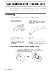
... lens cap was fitted onto the lens. Connections and Preparations This section describes how to install the projector and screen, how to project the picture, etc. Inserting them forcibly or with the polarities reversed may cause a short circuit and may generate heat. GB 12 Unpacking... Remove this lens cap when you use the projector. • Operating Instructions (this manual) (1) Inserting the batteries into the remote control ...
... lens cap was fitted onto the lens. Connections and Preparations This section describes how to install the projector and screen, how to project the picture, etc. Inserting them forcibly or with the polarities reversed may cause a short circuit and may generate heat. GB 12 Unpacking... Remove this lens cap when you use the projector. • Operating Instructions (this manual) (1) Inserting the batteries into the remote control ...

Operating Instructions
Page 15
... The installation distance between the center of the screen and the center of the projector's lens when using the maximum upper vertical lens shift feature. You can obtain a good quality picture if you position the projector with the center of the lens within the areas indicated in the gray areas ...in the table on the lens shift feature, see "Step 3: Adjusting the Picture Size and Position." (1 page 22) 15 Step 1: Installing...
... The installation distance between the center of the screen and the center of the projector's lens when using the maximum upper vertical lens shift feature. You can obtain a good quality picture if you position the projector with the center of the lens within the areas indicated in the gray areas ...in the table on the lens shift feature, see "Step 3: Adjusting the Picture Size and Position." (1 page 22) 15 Step 1: Installing...

Operating Instructions
Page 16
... Size) a (minimum) = 31.5 (1 1/4) × SS - 48.2 (1 15/16) b (maximum) = 53.8 (2 1/8) × SS - 46.9 (1 7/8) c = 8.0876 (11/32) × SS When using the 4:3 aspect ratio screen (projecting a 4:3 picture) Unit: mm (inches) Screen 40 60 80 100 120 150 180 200 250 300 size (inches) a 1494 2265 3036 3807 4578 5734 6891 7662 9590...) a (minimum) = 38.551 (1 9/16) × SS - 48.2 (1 15/16) b (maximum) = 65.842 (2 5/8) × SS - 46.9 (1 7/8) c = 9.8979 (13/32) × SS 16 GB Step 1: Installing the Projector
... Size) a (minimum) = 31.5 (1 1/4) × SS - 48.2 (1 15/16) b (maximum) = 53.8 (2 1/8) × SS - 46.9 (1 7/8) c = 8.0876 (11/32) × SS When using the 4:3 aspect ratio screen (projecting a 4:3 picture) Unit: mm (inches) Screen 40 60 80 100 120 150 180 200 250 300 size (inches) a 1494 2265 3036 3807 4578 5734 6891 7662 9590...) a (minimum) = 38.551 (1 9/16) × SS - 48.2 (1 15/16) b (maximum) = 65.842 (2 5/8) × SS - 46.9 (1 7/8) c = 9.8979 (13/32) × SS 16 GB Step 1: Installing the Projector

Operating Instructions
Page 17
...and Preparations 2 Position the projector so that it fits the screen. (1 page 22) To project an image, connect video equipment to the screen. Top view Screen 3 Project an image on the screen and adjust the picture so that the lens is not a malfunction of the projector on a ceiling, see... "Ceiling Installation." (1 page 76) 17 Step 1: Installing the Projector GB For installation of the...
...and Preparations 2 Position the projector so that it fits the screen. (1 page 22) To project an image, connect video equipment to the screen. Top view Screen 3 Project an image on the screen and adjust the picture so that the lens is not a malfunction of the projector on a ceiling, see... "Ceiling Installation." (1 page 76) 17 Step 1: Installing the Projector GB For installation of the...

Operating Instructions
Page 19
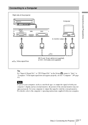
... of HDMI Licensing LLC. Connections and Preparations To connect to a DVD player/recorder equipped with HDMI output You can enjoy better picture quality by connecting a DVD player/recorder equipped with the HDMI output to HDMI output : Video signal flow HDMI cable (not supplied...) ...HDMI, HDMI logo and High-Definition Multimedia Interface are trademarks or registered trademarks of the projector. Right side of the projector AV amplifier Speakers INPUT PR INPUT A HDMI DVI-D TR DVD player/recorder, etc., with HDMI output to Ver. 1.1. ...
... of HDMI Licensing LLC. Connections and Preparations To connect to a DVD player/recorder equipped with HDMI output You can enjoy better picture quality by connecting a DVD player/recorder equipped with the HDMI output to HDMI output : Video signal flow HDMI cable (not supplied...) ...HDMI, HDMI logo and High-Definition Multimedia Interface are trademarks or registered trademarks of the projector. Right side of the projector AV amplifier Speakers INPUT PR INPUT A HDMI DVI-D TR DVD player/recorder, etc., with HDMI output to Ver. 1.1. ...

Operating Instructions
Page 20
...) or VIDEO INPUT (video input connector), connect it to S VIDEO to enjoy better picture quality. If the equipment to be connected has no S video connector, connect the cable to the video output. 20 GB Step 2: Connecting the Projector Connecting to Video Equipment You can connect a DVD player/recorder which connector you do...
...) or VIDEO INPUT (video input connector), connect it to S VIDEO to enjoy better picture quality. If the equipment to be connected has no S video connector, connect the cable to the video output. 20 GB Step 2: Connecting the Projector Connecting to Video Equipment You can connect a DVD player/recorder which connector you do...
Operating Instructions
Page 21
... output the signal to both your computer's display and an external monitor, the picture of the projector Computer to monitor output : Video signal flow HD D-sub 15-pin cable (not supplied), or DVI - Set your computer. 21 Step 2: Connecting the Projector GB or "DVI Signal Sel." in the Setup menu to only the external...
... output the signal to both your computer's display and an external monitor, the picture of the projector Computer to monitor output : Video signal flow HD D-sub 15-pin cable (not supplied), or DVI - Set your computer. 21 Step 2: Connecting the Projector GB or "DVI Signal Sel." in the Setup menu to only the external...

Operating Instructions
Page 22
Step 3: Adjusting the Picture Size and Position Project an image on /standby), INPUT, LENS, MENU, and M/m/ ON/STANDBY indicator Adjusters Remote control detector LIGHT INPUT DYNAMIC STANDARD CINEMA PICTURE MODE USER 1 USER 2 USER 3 4 2 5,6,7 ENTER LENS ADJ PIC MENU Tip The ?/1 (on the screen and then adjust the picture position.
Step 3: Adjusting the Picture Size and Position Project an image on /standby), INPUT, LENS, MENU, and M/m/ ON/STANDBY indicator Adjusters Remote control detector LIGHT INPUT DYNAMIC STANDARD CINEMA PICTURE MODE USER 1 USER 2 USER 3 4 2 5,6,7 ENTER LENS ADJ PIC MENU Tip The ?/1 (on the screen and then adjust the picture position.
Operating Instructions
Page 23
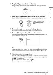
... 4 Press INPUT to the operating instructions of the signal input is automatically displayed by pressing the M/m/ Refer to project the picture on the projector. Press the LENS button repeatedly until the Lens Shift adjustment window (test pattern) appears. Connections and Preparations 1 Plug the AC...cord into standby mode. Then select the proper vertical position by pressing INPUT. (1 page 50) 5 Adjust the vertical picture position. ON/ STANDBY Lights in red and the projector goes into a wall outlet. The ON/STANDBY indicator lights in red. 2 Press the ?/1 (on/standby) switch ...
... 4 Press INPUT to the operating instructions of the signal input is automatically displayed by pressing the M/m/ Refer to project the picture on the projector. Press the LENS button repeatedly until the Lens Shift adjustment window (test pattern) appears. Connections and Preparations 1 Plug the AC...cord into standby mode. Then select the proper vertical position by pressing INPUT. (1 page 50) 5 Adjust the vertical picture position. ON/ STANDBY Lights in red and the projector goes into a wall outlet. The ON/STANDBY indicator lights in red. 2 Press the ?/1 (on/standby) switch ...

Operating Instructions
Page 24
For detailed information, see "Making Fine Adjustments to "Off" on page 83. 24 GB Step 3: Adjusting the Picture Size and Position Side view 0.65V 1V : Picture position when the picture is The picture moves up by a maximum of 0.65 of the screen size from the center of the lens. LENS Tip When "...Lens Control" is set to "Off" on the Installation adjust the vertical picture position. (1 page 51) When "Test Pattern" is set to the Horizontal Picture Position" on the Function not displayed. (1 page 50) menu, you cannot menu, the test pattern is moved ...
For detailed information, see "Making Fine Adjustments to "Off" on page 83. 24 GB Step 3: Adjusting the Picture Size and Position Side view 0.65V 1V : Picture position when the picture is The picture moves up by a maximum of 0.65 of the screen size from the center of the lens. LENS Tip When "...Lens Control" is set to "Off" on the Installation adjust the vertical picture position. (1 page 51) When "Test Pattern" is set to the Horizontal Picture Position" on the Function not displayed. (1 page 50) menu, you cannot menu, the test pattern is moved ...

Operating Instructions
Page 25
Press the LENS button repeatedly until the Lens Zoom adjustment window (test pattern) appears. Then adjust the size of the picture by pressing the M/ m/ Connections and Preparations 6 Adjust the picture size.
Press the LENS button repeatedly until the Lens Zoom adjustment window (test pattern) appears. Then adjust the size of the picture by pressing the M/ m/ Connections and Preparations 6 Adjust the picture size.

Operating Instructions
Page 26
Adjusters Note Be careful not to keep the projector level. To adjust the tilt of the installation surface If the projector is installed on an uneven surface, use the adjusters to catch your finger when turning the adjusters. 26 GB Step 3: Adjusting the Picture Size and Position Turn to adjust.
Adjusters Note Be careful not to keep the projector level. To adjust the tilt of the installation surface If the projector is installed on an uneven surface, use the adjusters to catch your finger when turning the adjusters. 26 GB Step 3: Adjusting the Picture Size and Position Turn to adjust.
Operating Instructions
Page 27
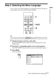
The factory default setting is English. LIGHT INPUT DYNAMIC STANDARD CINEMA PICTURE MODE USER 1 USER 2 USER 3 ENTER LENS ADJ PIC MENU WIDE MODE RCP RESET REAL COLOR PROCESSING BRIGHT CONTRAST 2 4,5,6 3 Tip You can select one of fifteen languages for displaying the menu and other onscreen displays. Connections and Preparations Step 4: Selecting the Menu Language You can operate the menu using the M/m/
The factory default setting is English. LIGHT INPUT DYNAMIC STANDARD CINEMA PICTURE MODE USER 1 USER 2 USER 3 ENTER LENS ADJ PIC MENU WIDE MODE RCP RESET REAL COLOR PROCESSING BRIGHT CONTRAST 2 4,5,6 3 Tip You can select one of fifteen languages for displaying the menu and other onscreen displays. Connections and Preparations Step 4: Selecting the Menu Language You can operate the menu using the M/m/

Operating Instructions
Page 28
... Sel. : Color System : On English Computer Video GBR Auto Installation Setup Information Sel: Set: Back: Exit: 5 Press M or m to select the Setup ENTER. oror ENTER Picture Signal Function Status : Language : Input-A Signal Sel. DVI Signal Sel. : Color System : On English Center Video GBR Auto Installation Setup Information Sel : Set : Exit : 6 Press...
... Sel. : Color System : On English Computer Video GBR Auto Installation Setup Information Sel: Set: Back: Exit: 5 Press M or m to select the Setup ENTER. oror ENTER Picture Signal Function Status : Language : Input-A Signal Sel. DVI Signal Sel. : Color System : On English Center Video GBR Auto Installation Setup Information Sel : Set : Exit : 6 Press...
Operating Instructions
Page 29
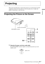
...indicator 4 LIGHT INPUT DYNAMIC STANDARD CINEMA PICTURE MODE USER 1 USER 2 USER 3 2 5,6 ENTER LENS ADJ PIC MENU 1 Plug the AC power cord into standby mode. ON/ STANDBY Lights in red and the projector goes into a wall outlet. Projecting the Picture on the Screen GB It also ...describes how to adjust the quality of the picture to the projector. Projecting This section describes how to operate the projector to view the picture from the equipment connected to ...
...indicator 4 LIGHT INPUT DYNAMIC STANDARD CINEMA PICTURE MODE USER 1 USER 2 USER 3 2 5,6 ENTER LENS ADJ PIC MENU 1 Plug the AC power cord into standby mode. ON/ STANDBY Lights in red and the projector goes into a wall outlet. Projecting the Picture on the Screen GB It also ...describes how to adjust the quality of the picture to the projector. Projecting This section describes how to operate the projector to view the picture from the equipment connected to ...
Operating Instructions
Page 30
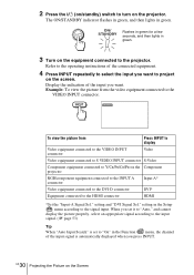
2 Press the ?/1 (on/standby) switch to turn on the equipment connected to the projector. setting and "DVI Signal Sel." Example: To view the picture from Press INPUT to display Video equipment connected to the VIDEO INPUT connector Video Video equipment connected to S VIDEO ...the Function menu, the channel of the connected equipment. 4 Press INPUT repeatedly to select the input you want to project on the Component projector RGB/component equipment connected to the INPUT A connector Input-A* Video equipment connected to the DVI-D connector DVI* Equipment connected to Y/CB/PB...
2 Press the ?/1 (on/standby) switch to turn on the equipment connected to the projector. setting and "DVI Signal Sel." Example: To view the picture from Press INPUT to display Video equipment connected to the VIDEO INPUT connector Video Video equipment connected to S VIDEO ...the Function menu, the channel of the connected equipment. 4 Press INPUT repeatedly to select the input you want to project on the Component projector RGB/component equipment connected to the INPUT A connector Input-A* Video equipment connected to the DVI-D connector DVI* Equipment connected to Y/CB/PB...

