User Guide
Page 1
TEG-S224 Series Stackable NWay Ethernet Switch User's Guide First Edition (Feb. 2000) Printed In Taiwan RECYCLABLE
TEG-S224 Series Stackable NWay Ethernet Switch User's Guide First Edition (Feb. 2000) Printed In Taiwan RECYCLABLE

User Guide
Page 12
.... Stackable NWay Ethernet Switch User's Guide 0 ABOUT THIS GUIDE This User's Guide tells you get started with the basic installation of this manual to the TEG-S224 Series are frequently written simply as "Switch" or "Switches" where the text applies to all models. Model numbers are normally used only to all models...
.... Stackable NWay Ethernet Switch User's Guide 0 ABOUT THIS GUIDE This User's Guide tells you get started with the basic installation of this manual to the TEG-S224 Series are frequently written simply as "Switch" or "Switches" where the text applies to all models. Model numbers are normally used only to all models...

User Guide
Page 18
... two MDI-II/MDI-X jack connections are designed for uplink to most kinds of local area network congestion problems. Features The TEG-S224 series of users increases continuously. Gigabit uplink/MDI-II (media dependent interface) slide-in module in the rear panel for easy... NWay Ethernet Switch User's Guide required make routers relatively impractical. They are supported) (TEG-S224S and TEG-S224SF). ? ? All ports can include one MDI-II/MDI-X jack connection are supported) (TEG-S224M and TEG-S224MF) or 22 high performance NWay ports all operating at 10/100 Mbps for connection...
... two MDI-II/MDI-X jack connections are designed for uplink to most kinds of local area network congestion problems. Features The TEG-S224 series of users increases continuously. Gigabit uplink/MDI-II (media dependent interface) slide-in module in the rear panel for easy... NWay Ethernet Switch User's Guide required make routers relatively impractical. They are supported) (TEG-S224S and TEG-S224SF). ? ? All ports can include one MDI-II/MDI-X jack connection are supported) (TEG-S224M and TEG-S224MF) or 22 high performance NWay ports all operating at 10/100 Mbps for connection...
User Guide
Page 23
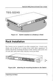
To install, attach the mounting brackets on the switch's front panel (one on a Desktop or Shelf Rack Installation The Switch can be mounted in an EIA standard size, 19-inch rack, which can be placed in a wiring closet with the screws provided. Attaching the mounting brackets to the Switch Unpacking and Setup 9 Stackable NWay Ethernet Switch User's Guide TEG-S224S Figure 2-1. Switch installed on each side) and secure them with other equipment. Figure 2-2A.
To install, attach the mounting brackets on the switch's front panel (one on a Desktop or Shelf Rack Installation The Switch can be mounted in an EIA standard size, 19-inch rack, which can be placed in a wiring closet with the screws provided. Attaching the mounting brackets to the Switch Unpacking and Setup 9 Stackable NWay Ethernet Switch User's Guide TEG-S224S Figure 2-1. Switch installed on each side) and secure them with other equipment. Figure 2-2A.

User Guide
Page 26
...Fast Ethernet ports, one or two uplink jacks, a slidein module slot for 10/100 Mbps Ethernet ports, an RS-232 communication port (TEG-S224M and TEG-S224MF only), and LED indicators. TEG-S224S Power Slot1 Slot2 S i o 1 S i o 2 Sio3 Slot1 Uplink 1x 3x 5x 7x 9x 11x 13x 15x 17x 19x ...21x Uplink 2x 4x 6x 8x 10x 12x 14x 16x 18x 20x 22x TEG-S224M Power Console Slot1 Slot3 Giga1Giga2 Slot2 Sio1 S i o 2 S i o 3 RS-232DCE,9600,n,8,1 ...
...Fast Ethernet ports, one or two uplink jacks, a slidein module slot for 10/100 Mbps Ethernet ports, an RS-232 communication port (TEG-S224M and TEG-S224MF only), and LED indicators. TEG-S224S Power Slot1 Slot2 S i o 1 S i o 2 Sio3 Slot1 Uplink 1x 3x 5x 7x 9x 11x 13x 15x 17x 19x ...21x Uplink 2x 4x 6x 8x 10x 12x 14x 16x 18x 20x 22x TEG-S224M Power Console Slot1 Slot3 Giga1Giga2 Slot2 Sio1 S i o 2 S i o 3 RS-232DCE,9600,n,8,1 ...

User Guide
Page 27
... Identifying External Components 13 All ports can accommodate the following shows the rear panel of the Switches. Port number 1 on the TEG-S224S and the TEG-S224SF are equipped with MDI-X jacks for normal end-node connections and MDI-II jacks for a Stacking input/output port and ... of a slot (labeled Slot2) for uplink connections. One or two MDI-II uplink jacks are supported. Rear Panel The rear panel of the TEG-S224S and the TEG-S224SF consist of these LED indicators follows (see LED Indicators). ? ? A slide-in module slot (labeled Slot1) for an optional Gigabit Ethernet ...
... Identifying External Components 13 All ports can accommodate the following shows the rear panel of the Switches. Port number 1 on the TEG-S224S and the TEG-S224SF are equipped with MDI-X jacks for normal end-node connections and MDI-II jacks for a Stacking input/output port and ... of a slot (labeled Slot2) for uplink connections. One or two MDI-II uplink jacks are supported. Rear Panel The rear panel of the TEG-S224S and the TEG-S224SF consist of these LED indicators follows (see LED Indicators). ? ? A slide-in module slot (labeled Slot1) for an optional Gigabit Ethernet ...

User Guide
Page 28
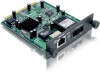
The Stacking input/output port slide-in module in the rear panel is for uplink to another device to another Switch (TEG-S224M and TEG-S224MF only). The three-port module is an uplink/MDI-II (media dependent interface) port for stacking to implement a highport count, ...below). Two models are available, one -port module is a three-pronged connector that supports the power cord. Stackable NWay Ethernet Switch User's Guide TEG-S224M TEG-S224S Figure 3-2. The optional Gigabit Ethernet slide-in the female connector of the provided power cord into this connector, and the male into a power ...
The Stacking input/output port slide-in module in the rear panel is for uplink to another device to another Switch (TEG-S224M and TEG-S224MF only). The three-port module is an uplink/MDI-II (media dependent interface) port for stacking to implement a highport count, ...below). Two models are available, one -port module is a three-pronged connector that supports the power cord. Stackable NWay Ethernet Switch User's Guide TEG-S224M TEG-S224S Figure 3-2. The optional Gigabit Ethernet slide-in the female connector of the provided power cord into this connector, and the male into a power ...

User Guide
Page 29
...without proper heat dissipation and air circulation, system components might overheat, which could lead to by unit ID and port number in your TEG-S224 Series stack. Identifying External Components 15 Stackable NWay Ethernet Switch User's Guide Figure 3-3. Each port is referred to system failure. Once ...stack, a one-port Stacking input/output module is needed for each client Switch to serve the same purpose. Stack Operation The TEG-S224M and the TEG-S224MF are used to three client Switches (TEGS224S and TEG-S224SF). The sides of the Switch ? ? To set up to dissipate heat.
...without proper heat dissipation and air circulation, system components might overheat, which could lead to by unit ID and port number in your TEG-S224 Series stack. Identifying External Components 15 Stackable NWay Ethernet Switch User's Guide Figure 3-3. Each port is referred to system failure. Once ...stack, a one-port Stacking input/output module is needed for each client Switch to serve the same purpose. Stack Operation The TEG-S224M and the TEG-S224MF are used to three client Switches (TEGS224S and TEG-S224SF). The sides of the Switch ? ? To set up to dissipate heat.

User Guide
Page 30
Switch stack with one master and three clients Please note that two client switches can also be connected via the Stacking input/output ports. The following diagram displays some possible switch stack connections: 16 Identifying External Components Stackable NWay Ethernet Switch User's Guide TEG-S224M TEG-S224S Figure 3-4.
Switch stack with one master and three clients Please note that two client switches can also be connected via the Stacking input/output ports. The following diagram displays some possible switch stack connections: 16 Identifying External Components Stackable NWay Ethernet Switch User's Guide TEG-S224M TEG-S224S Figure 3-4.

User Guide
Page 31
Switch stack with example of possible connections Optional Plug-in Modules The TEG-S224M/TEG-S224MF Stackable NWay Ethernet Switch is able to accommodate a range of plug-in modules in order to increase functionality and performance. Stackable NWay Ethernet Switch ...User's Guide Local 10Mbps printer 10/100Mbps Hub pc Local pc 10Mbps printer TEG-S224M Local 10Mbps printer pc Local 10Mbps printer Local 100Mbps server pc 10/100Mbps Hub TEG-S224S 10/100Mbps Hub Local 10Mbps printer pc Local 10Mbps printer pc 10/100Mbps Hub Local 100Mbps server Local...
Switch stack with example of possible connections Optional Plug-in Modules The TEG-S224M/TEG-S224MF Stackable NWay Ethernet Switch is able to accommodate a range of plug-in modules in order to increase functionality and performance. Stackable NWay Ethernet Switch ...User's Guide Local 10Mbps printer 10/100Mbps Hub pc Local pc 10Mbps printer TEG-S224M Local 10Mbps printer pc Local 10Mbps printer Local 100Mbps server pc 10/100Mbps Hub TEG-S224S 10/100Mbps Hub Local 10Mbps printer pc Local 10Mbps printer pc 10/100Mbps Hub Local 100Mbps server Local...
User Guide
Page 32
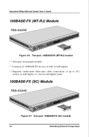
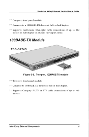
Two-port, front-panel module. ? ? or half-duplex. ? ? One-port, 100BASE-FX (SC) module 18 Identifying External Components Supports multi-mode fiber-optic cable connections of up to 100BASE-FX devices at full- Two-port, 100BASE-FX (MT-RJ) module ? ? Connects to 412 meters in half-duplex or 2 km in full-duplex mode. 100BASE-FX (SC) Module TEG-S224S Figure 3-7. Stackable NWay Ethernet Switch User's Guide 100BASE-FX (MT-RJ) Module TEG-S224S Figure 3-6.
Two-port, front-panel module. ? ? or half-duplex. ? ? One-port, 100BASE-FX (SC) module 18 Identifying External Components Supports multi-mode fiber-optic cable connections of up to 100BASE-FX devices at full- Two-port, 100BASE-FX (MT-RJ) module ? ? Connects to 412 meters in half-duplex or 2 km in full-duplex mode. 100BASE-FX (SC) Module TEG-S224S Figure 3-7. Stackable NWay Ethernet Switch User's Guide 100BASE-FX (MT-RJ) Module TEG-S224S Figure 3-6.
User Guide
Page 33
Two-port, 100BASE-TX module ? ? Connects to 412 meters in half-duplex or 2 km in full-duplex mode. 100BASE-TX Module TEG-S224S Figure 3-8. or half-duplex. ? ? Two-port, front-panel module. ? ? Identifying External Components 19 Supports multi-mode fiber-optic cable connections of up to 100BASE-TX devices at full- Supports Category 5 UTP or STP cable connections of up to a 100BASE-FX device at full or half duplex. ? ? Stackable NWay Ethernet Switch User's Guide ? ? One-port, front panel module. ? ? Connects to 100 meters.
Two-port, 100BASE-TX module ? ? Connects to 412 meters in half-duplex or 2 km in full-duplex mode. 100BASE-TX Module TEG-S224S Figure 3-8. or half-duplex. ? ? Two-port, front-panel module. ? ? Identifying External Components 19 Supports multi-mode fiber-optic cable connections of up to 100BASE-TX devices at full- Supports Category 5 UTP or STP cable connections of up to a 100BASE-FX device at full or half duplex. ? ? Stackable NWay Ethernet Switch User's Guide ? ? One-port, front panel module. ? ? Connects to 100 meters.
User Guide
Page 36
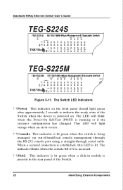
...) is accessed. ? ? The indicator blinks when the console RS-232 is running or if the system's configuration has changed. Stackable NWay Ethernet Switch User's Guide TEG-S224S TEG-S225M RS-2 Figure 3-11.
...) is accessed. ? ? The indicator blinks when the console RS-232 is running or if the system's configuration has changed. Stackable NWay Ethernet Switch User's Guide TEG-S224S TEG-S225M RS-2 Figure 3-11.
User Guide
Page 39
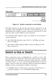
... important consideration is that is connected to are not illuminated after making a proper connection, check the PC's LAN card, the cable, switch conditions, and connections. TEG-S224S Stackable NWay Ethernet Switch User's Guide Slot1 Uplink 1x 3x 5x 7x 9x 11x 13x 15x 17x 19x 21x Uplink 2x 4x 6x 8x 10x...
... important consideration is that is connected to are not illuminated after making a proper connection, check the PC's LAN card, the cable, switch conditions, and connections. TEG-S224S Stackable NWay Ethernet Switch User's Guide Slot1 Uplink 1x 3x 5x 7x 9x 11x 13x 15x 17x 19x 21x Uplink 2x 4x 6x 8x 10x...

User Guide
Page 77
... local network, you do not want the Switch to set the bit rate used for a Class C network. ? ? Should be sent. Subnet Mask Bitmask that the TEG-S224M has an RS-232C serial port but the TEG-S224S does not. The following screen appears: Using the Console Interface 63
... local network, you do not want the Switch to set the bit rate used for a Class C network. ? ? Should be sent. Subnet Mask Bitmask that the TEG-S224M has an RS-232C serial port but the TEG-S224S does not. The following screen appears: Using the Console Interface 63

User Guide
Page 135
... installed on the desired Switch to view that allows a person to configure the IP interface of the switch. The second and last step is to TEG-S224 Manager button: This opens the main page in the "Using The Console Interface" chapter). The URL in the address bar should read hypertext, for the...
... installed on the desired Switch to view that allows a person to configure the IP interface of the switch. The second and last step is to TEG-S224 Manager button: This opens the main page in the "Using The Console Interface" chapter). The URL in the address bar should read hypertext, for the...
User Guide
Page 194
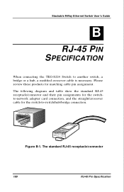
Stackable NWay Ethernet Switch User's Guide B 9 RJ-45 PIN SPECIFICATION When connecting the TEG-S224 Switch to -switch/hub/bridge connection. Figure B-1. The following diagram and table show the standard RJ-45 receptacle/connector and their pin assignments for the switchto-network adapter card connection, and the straight/crossover cable for matching cable pin assignment. The standard RJ-45 receptacle/connector 180 RJ-45 Pin Specification Please review these products for the switch-to another switch, a bridge or a hub, a modified crossover cable is necessary.
Stackable NWay Ethernet Switch User's Guide B 9 RJ-45 PIN SPECIFICATION When connecting the TEG-S224 Switch to -switch/hub/bridge connection. Figure B-1. The following diagram and table show the standard RJ-45 receptacle/connector and their pin assignments for the switchto-network adapter card connection, and the straight/crossover cable for matching cable pin assignment. The standard RJ-45 receptacle/connector 180 RJ-45 Pin Specification Please review these products for the switch-to another switch, a bridge or a hub, a modified crossover cable is necessary.