
Data Sheet
Page 1
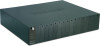
...-Play and Hot-Swap features allow installing/removing the converter unit without powering off the chassis. fiber 16-Slot Chassis System for TFC series Fiber Converter TFC-1600 TRENDnet's TFC-1600 16-slot EIA-19" Rack-Mount Chassis System provides housing for up to 16 TFC series media converters • Front panel LEDs indication tiation Mode for Fiber Port •...
...-Play and Hot-Swap features allow installing/removing the converter unit without powering off the chassis. fiber 16-Slot Chassis System for TFC series Fiber Converter TFC-1600 TRENDnet's TFC-1600 16-slot EIA-19" Rack-Mount Chassis System provides housing for up to 16 TFC series media converters • Front panel LEDs indication tiation Mode for Fiber Port •...

Data Sheet
Page 2
... and product names are trademarks of their respective holders. Information provided in this document pertain to TRENDnet products and is a registered trademark. 16-Slot Chassis System for TFC series Fiber Converter TFC-1600 SPECIFICATIONS Hardware Capacity • 16 slots for TFC-1600 ORDERING INFORMATION 20675 Manhattan Place,Torrance, CA 90501 USA Tel: 1-310-961-5500 Fax: 1-310...
... and product names are trademarks of their respective holders. Information provided in this document pertain to TRENDnet products and is a registered trademark. 16-Slot Chassis System for TFC series Fiber Converter TFC-1600 SPECIFICATIONS Hardware Capacity • 16 slots for TFC-1600 ORDERING INFORMATION 20675 Manhattan Place,Torrance, CA 90501 USA Tel: 1-310-961-5500 Fax: 1-310...

Manual
Page 5
Installing and Removing the Power Supply 11 UNDERSTANDING LED INDICATORS......... 12 FRONT PANEL 12 POWER AND FAN LED 12 TECHNICAL SPECIFICATIONS 13 ORDERING INFORMATION 15 1. 100TX ~ 100FX MEDIA CONVERTER 15 2. 10/100TX ~ 100FX MEDIA CONVERTER 16 i Connecting to 19-inch standard rack 8 . Mounted to Power (Power Supply 10 . Installing Media Converter 9 . TABLE OF CONTENTS PREFACE 3 19" MEDIA CONVERTER CHASSIS SYSTEM 4 PRODUCT FEATURES 5 PRODUCT FEATURES 5 UNPACKING AND INSTALLATION 6 UNPACKING 6 INSTALLATION 6 DECIDING HOW TO INSTALL THE SYSTEM 7 .
Installing and Removing the Power Supply 11 UNDERSTANDING LED INDICATORS......... 12 FRONT PANEL 12 POWER AND FAN LED 12 TECHNICAL SPECIFICATIONS 13 ORDERING INFORMATION 15 1. 100TX ~ 100FX MEDIA CONVERTER 15 2. 10/100TX ~ 100FX MEDIA CONVERTER 16 i Connecting to 19-inch standard rack 8 . Mounted to Power (Power Supply 10 . Installing Media Converter 9 . TABLE OF CONTENTS PREFACE 3 19" MEDIA CONVERTER CHASSIS SYSTEM 4 PRODUCT FEATURES 5 PRODUCT FEATURES 5 UNPACKING AND INSTALLATION 6 UNPACKING 6 INSTALLATION 6 DECIDING HOW TO INSTALL THE SYSTEM 7 .

Manual
Page 7
...media conversion solution. single-mode) ? 1000BASE-SX/LX ? 1000BASE-LX (multi-mode ? Ordering Information Attention! The chassis shown in the figures of which offers one power supply. You can order the proprietary media converters and a second ...power supply separately. 3 Below is a list of the Chassis System ?? Product features ?? The chassis comes with redundant power supplies. Illustrative LEDs functions ?? Installation instructions ?? Specifications ?? Introduction of the available media conversions...
...media conversion solution. single-mode) ? 1000BASE-SX/LX ? 1000BASE-LX (multi-mode ? Ordering Information Attention! The chassis shown in the figures of which offers one power supply. You can order the proprietary media converters and a second ...power supply separately. 3 Below is a list of the Chassis System ?? Product features ?? The chassis comes with redundant power supplies. Illustrative LEDs functions ?? Installation instructions ?? Specifications ?? Introduction of the available media conversions...

Manual
Page 8
Proprietary media converters and a second power supply are not included! 4 The chassis system ships with two power supplies and sixteen media converters. Attention! 19" Media Converter Chassis System The chassis can be equipped with only one power supply.
Proprietary media converters and a second power supply are not included! 4 The chassis system ships with two power supplies and sixteen media converters. Attention! 19" Media Converter Chassis System The chassis can be equipped with only one power supply.

Manual
Page 9
... LEDs for load-sharing ?? Media Converter Power Isolation; The following items are electrically isolated from each other power supply is capable of the Media Converter Chassis System. Power redundancy & power isolation ??
... LEDs for load-sharing ?? Media Converter Power Isolation; The following items are electrically isolated from each other power supply is capable of the Media Converter Chassis System. Power redundancy & power isolation ??

Manual
Page 10
...One AC power cord ?? Installation The site where you shall find these items listed below. ?? 19" Media Converter Chassis System ?? Unpacking When unpacking the product package, you place the chassis system may greatly affect its performance. Accessories: rack -mount screws (8 pcs.), rack -mount ears (2 pcs.), ...rubber foot (4 pcs.) If any damage to the Chassis, we recommend that you read this chapter carefully before starting installation. User's Manual ?? To avoid causing any item is found missing ...
...One AC power cord ?? Installation The site where you shall find these items listed below. ?? 19" Media Converter Chassis System ?? Unpacking When unpacking the product package, you place the chassis system may greatly affect its performance. Accessories: rack -mount screws (8 pcs.), rack -mount ears (2 pcs.), ...rubber foot (4 pcs.) If any damage to the Chassis, we recommend that you read this chapter carefully before starting installation. User's Manual ?? To avoid causing any item is found missing ...

Manual
Page 11
The site you selected should not exceed the electromagnetic field (RFC) standards for you to install media converters into the chassis with any electric device, you install the chassis first, as this is more convenient for IEC 801-3, Level 2 (3V/M) field strength. - Do not block ...the fan exhaust holes on the rear of the chassis. This wellbuilt chassis can be installed in the product package include: rackmount screws (8 pcs.) and rack-mount brackets (2 pcs.). Surrounding electrical devices should meet...
The site you selected should not exceed the electromagnetic field (RFC) standards for you to install media converters into the chassis with any electric device, you install the chassis first, as this is more convenient for IEC 801-3, Level 2 (3V/M) field strength. - Do not block ...the fan exhaust holes on the rear of the chassis. This wellbuilt chassis can be installed in the product package include: rackmount screws (8 pcs.) and rack-mount brackets (2 pcs.). Surrounding electrical devices should meet...

Manual
Page 12
Step 3: Proceed to the "Connecting to both sides of the chassis. Step 2: Carefully position the chassis into any EIA 19" standard rack. Step 1: Attach the brackets to Power" section. 8 Align the brackets to the screw holes on the rack. Apply four screws to secure the chassis on the rack and use rack screws to each side and secure them. .Mounting to 19-inch standard rack Use the rack-mount brackets and screws to install the chassis into the rack.
Step 3: Proceed to the "Connecting to both sides of the chassis. Step 2: Carefully position the chassis into any EIA 19" standard rack. Step 1: Attach the brackets to Power" section. 8 Align the brackets to the screw holes on the rack. Apply four screws to secure the chassis on the rack and use rack screws to each side and secure them. .Mounting to 19-inch standard rack Use the rack-mount brackets and screws to install the chassis into the rack.

Manual
Page 13
...out on the carrier Step 3: Carefully slide in the module and fasten the thumbscrew clockwise until it is fitted into bays of the chassis. Step 1: To install a media converter module onto the chassis, you have to unscrew the bay cover from the desired bay first. .Installing Media Converter The... chassis is equipped with sixteen media converter carriers, each of which is fully and firmly fitted into the slot of the chassis. Step 2: Unscrew the thumbscrew counter clockwise and pull the media converter out of the...
...out on the carrier Step 3: Carefully slide in the module and fasten the thumbscrew clockwise until it is fitted into bays of the chassis. Step 1: To install a media converter module onto the chassis, you have to unscrew the bay cover from the desired bay first. .Installing Media Converter The... chassis is equipped with sixteen media converter carriers, each of which is fully and firmly fitted into the slot of the chassis. Step 2: Unscrew the thumbscrew counter clockwise and pull the media converter out of the...

Manual
Page 14
...There is equipped with only one power supply is the best solution to function. ? ? When the chassis is an optional solution for the backup power, 48 volt DC to Power (Power Supply) The chassis ships with two power supplies, you may remove any connection loss. The power of each converter bay... comes from the Chassis, the chassis will instantaneously take 100% of the load without any one of providing maximum flexibility and redundancy. An optional second power supply is available. Hot ...
...There is equipped with only one power supply is the best solution to function. ? ? When the chassis is an optional solution for the backup power, 48 volt DC to Power (Power Supply) The chassis ships with two power supplies, you may remove any connection loss. The power of each converter bay... comes from the Chassis, the chassis will instantaneously take 100% of the load without any one of providing maximum flexibility and redundancy. An optional second power supply is available. Hot ...

Manual
Page 15
...screwdriver. The Power LED on the front panel will come on a sturdy flat surface, 11 The chassis system is equipped with the guides on the chassis, slide in the power supply to the chassis, and then tighten the thumbscrews by turning them counter clockwise and then pull out the power supply... bay, fasten or loose the hand screw clockwise or counter clockwise by flipping the switch beside the power cord receptacle to the back of the chassis. To remove a power supply, loosen the two thumbscrews by turning them clockwise. Step 2: Attach the plug into a standard AC outlet with two...
...screwdriver. The Power LED on the front panel will come on a sturdy flat surface, 11 The chassis system is equipped with the guides on the chassis, slide in the power supply to the chassis, and then tighten the thumbscrews by turning them counter clockwise and then pull out the power supply... bay, fasten or loose the hand screw clockwise or counter clockwise by flipping the switch beside the power cord receptacle to the back of the chassis. To remove a power supply, loosen the two thumbscrews by turning them clockwise. Step 2: Attach the plug into a standard AC outlet with two...

Manual
Page 16
... (Amber) Off Faulty Fan Fan works normally 12 UNDERSTANDING LED INDICATORS The front panel LEDs provide instant operating status and help monitor and troubleshoot the Chassis. Front Panel There are six LED indicators that provide you with instant feedback on the status of the... Chassis (one at each corner) and then place the Chassis on which slot the power supply is working (depends on the flat surface. attached the rubber foot on the bottom of the power supply and...
... (Amber) Off Faulty Fan Fan works normally 12 UNDERSTANDING LED INDICATORS The front panel LEDs provide instant operating status and help monitor and troubleshoot the Chassis. Front Panel There are six LED indicators that provide you with instant feedback on the status of the... Chassis (one at each corner) and then place the Chassis on which slot the power supply is working (depends on the flat surface. attached the rubber foot on the bottom of the power supply and...

Manual
Page 17
Two fans. 2 LEDs for fan status 2 LEDs for power on/off status 2 LEDs for load-sharing/redundancy is also available. TECHNICAL SPECIFICATIONS Capacity Material Power Cooling LED Indicators Dimensions Net Weight Chassis System Sixteen bays for housing up to sixteen media converters Sheet Metal One hot-swappable power supply. *A second power supply (optional) for power supply's status 415 mm × 390mm × 89 mm (W × D × H) Standard 19" size, 2 Unit Height 7.0kg approx. (*with one power supply) 13
Two fans. 2 LEDs for fan status 2 LEDs for power on/off status 2 LEDs for load-sharing/redundancy is also available. TECHNICAL SPECIFICATIONS Capacity Material Power Cooling LED Indicators Dimensions Net Weight Chassis System Sixteen bays for housing up to sixteen media converters Sheet Metal One hot-swappable power supply. *A second power supply (optional) for power supply's status 415 mm × 390mm × 89 mm (W × D × H) Standard 19" size, 2 Unit Height 7.0kg approx. (*with one power supply) 13

Manual
Page 22
... 20km 6. Power Supply Power Type 6-1 150 Watt AC to DC Power Supply 6-2 -48 Volt DC to DC Power Supply 7. Management Module 7-1 Management module for the Chassis System (manage/monitor chassis status via console port or Ethernet port with SNMP software) 18
... 20km 6. Power Supply Power Type 6-1 150 Watt AC to DC Power Supply 6-2 -48 Volt DC to DC Power Supply 7. Management Module 7-1 Management module for the Chassis System (manage/monitor chassis status via console port or Ethernet port with SNMP software) 18