
Use and Care Manual
Page 9
..., see chapter "Special functions", section "Vacation mode". Signal to switch vacation mode on the display panel in the display panel. Controls en-us A On/Off button Serves to switch the whole appliance on and off. F Display panel The temperatures in the refrigerator compartment and in the freezer compartment are shown via "symbol". If...
..., see chapter "Special functions", section "Vacation mode". Signal to switch vacation mode on the display panel in the display panel. Controls en-us A On/Off button Serves to switch the whole appliance on and off. F Display panel The temperatures in the refrigerator compartment and in the freezer compartment are shown via "symbol". If...

Use and Care Manual
Page 10
The appliance begins to change the display language: 1. The factory has recommended the following message lights up in the display panel: Set the language The display languages can be selected from +35 °F to the appliance or the furniture fronts, fold the rail when closing the ...
The appliance begins to change the display language: 1. The factory has recommended the following message lights up in the display panel: Set the language The display languages can be selected from +35 °F to the appliance or the furniture fronts, fold the rail when closing the ...

Use and Care Manual
Page 11
... is switched on , the following settings are made . Press Vacation button. 3. The previous settings and temperature values are once again activated. Switching on the display panel and SABBATH is pressed ■ Interior light ■ Background illumination of the changed settings are stored. The VACATION symbol flashes on Press Vacation button. Switching...
... is switched on , the following settings are made . Press Vacation button. 3. The previous settings and temperature values are once again activated. Switching on the display panel and SABBATH is pressed ■ Interior light ■ Background illumination of the changed settings are stored. The VACATION symbol flashes on Press Vacation button. Switching...

Use and Care Manual
Page 12
... attention to cool down before placing in the appliance. ■ Do not block air outlet openings with the plastic parts and door seal. The display panel indicates the symbol SUPER¾ and the compartment for ready products and bottled products. 12 Arranging food in the appliance ■ Wrap or cover food...
... attention to cool down before placing in the appliance. ■ Do not block air outlet openings with the plastic parts and door seal. The display panel indicates the symbol SUPER¾ and the compartment for ready products and bottled products. 12 Arranging food in the appliance ■ Wrap or cover food...

Use and Care Manual
Page 14
...The ice maker can make ice cubes as soon as possible in the microwave. Switching on super freezing several hours beforehand. The display panel indicates the symbol SUPER¾ and the compartment for the max. No longer store the frozen produce for which is its place and ...locked into position. 2. Press ice maker button . The symbol ICE is lit on the display panel. 1. Make sure that ice maker container is automatically restored. To prevent an undesirable temperature rise when placing fresh food in order to make...
...The ice maker can make ice cubes as soon as possible in the microwave. Switching on super freezing several hours beforehand. The display panel indicates the symbol SUPER¾ and the compartment for the max. No longer store the frozen produce for which is its place and ...locked into position. 2. Press ice maker button . The symbol ICE is lit on the display panel. 1. Make sure that ice maker container is automatically restored. To prevent an undesirable temperature rise when placing fresh food in order to make...

Use and Care Manual
Page 20
... the shut-off tap incorrectly opened . Change the water filter. 20 The appliance or ice maker has only just been switched on at the control panel. The water filter is bunged up or used . Incorrect shut-off tap fully. Temperature in the freezer space is not properly sealed. The water connection...
... the shut-off tap incorrectly opened . Change the water filter. 20 The appliance or ice maker has only just been switched on at the control panel. The water filter is bunged up or used . Incorrect shut-off tap fully. Temperature in the freezer space is not properly sealed. The water connection...
Installation Manual
Page 4
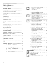
... Pushing the appliance into the installation enclosure 15 1. Aligning the base panel 18 3. Removing the positioning aid 19 7. Attaching the adjusting rail to the door panel (refrigerator compartment 20 9. Attaching the door panel (freezer compartment 24 13. Attaching an edge protection 14 4. Attaching ... installation enclosure 16 2. Attaching the appliance to the appliance 27 Adjusting the door opening angle 27 4 Attaching the toe kick panel 18 2. Switching the appliance ON 19 4. Adjusting the door spring 26 Special installation 27 Preparing to connect the water 27 ...
... Pushing the appliance into the installation enclosure 15 1. Aligning the base panel 18 3. Removing the positioning aid 19 7. Attaching the adjusting rail to the door panel (refrigerator compartment 20 9. Attaching the door panel (freezer compartment 24 13. Attaching an edge protection 14 4. Attaching ... installation enclosure 16 2. Attaching the appliance to the appliance 27 Adjusting the door opening angle 27 4 Attaching the toe kick panel 18 2. Switching the appliance ON 19 4. Adjusting the door spring 26 Special installation 27 Preparing to connect the water 27 ...
Installation Manual
Page 6
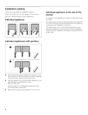
... be used. See the section on "Required accessories and tools/Optional accessories". Minimum thickness of the side panel are opened at the end of the kitchen If one side of the appliance is placed in the installation enclosure. See also "Kitchen Design Quick ... at the same time. Use the Heater Kit for Side-by the design of the door panels to the wall, the floor and overhead cabinet/fixtures before the appliance is visible, a side panel must be connected firmly to prevent damage if the doors are taken from the opposite installation enclosure wall...
... be used. See the section on "Required accessories and tools/Optional accessories". Minimum thickness of the side panel are opened at the end of the kitchen If one side of the appliance is placed in the installation enclosure. See also "Kitchen Design Quick ... at the same time. Use the Heater Kit for Side-by the design of the door panels to the wall, the floor and overhead cabinet/fixtures before the appliance is visible, a side panel must be connected firmly to prevent damage if the doors are taken from the opposite installation enclosure wall...

Installation Manual
Page 7
... of the installation enclosure, this may not close properly. 7 The safest method of a hard, rigid material. Installation enclosure Note: It is strongly recommended the top panel of the niche be made of installing the appliance in the installation area must be of the room (no possibility of a fully loaded appliance, a load...
... of the installation enclosure, this may not close properly. 7 The safest method of a hard, rigid material. Installation enclosure Note: It is strongly recommended the top panel of the niche be made of installing the appliance in the installation area must be of the room (no possibility of a fully loaded appliance, a load...
Installation Manual
Page 9
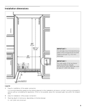
... the power connection C Opening depth of the enclosure must be of solid material at least 4" (100 mm) deep. If this is strongly recommended the top panel of the enclosure be perfectly straight. Legend: A Area for installation of the water connection It is recommended the water-box be placed adjacent to be...
... the power connection C Opening depth of the enclosure must be of solid material at least 4" (100 mm) deep. If this is strongly recommended the top panel of the enclosure be perfectly straight. Legend: A Area for installation of the water connection It is recommended the water-box be placed adjacent to be...
Installation Manual
Page 10
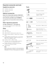
... Wooden beam (cross section min. 3" x 4") as an alternative tilt protection, length according to the width of two door panels. protective sheets) Adhesive tape Note: Before using, check whether the removed adhesive tape leaves adhesive residue on high-quality work ...drill for drilling holes in different sizes Thin (max. 1/16" (1.5 mm)), suitable material to protect the floor from damage (e.g. Panel unification part (Metal strip) FPCONNBF10 For connection of the installation cavity Wooden screws in wall or floor Bits according suitable ...
... Wooden beam (cross section min. 3" x 4") as an alternative tilt protection, length according to the width of two door panels. protective sheets) Adhesive tape Note: Before using, check whether the removed adhesive tape leaves adhesive residue on high-quality work ...drill for drilling holes in different sizes Thin (max. 1/16" (1.5 mm)), suitable material to protect the floor from damage (e.g. Panel unification part (Metal strip) FPCONNBF10 For connection of the installation cavity Wooden screws in wall or floor Bits according suitable ...
Installation Manual
Page 12
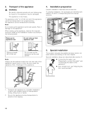
... appliance, observe the required minimum height at the installation location according to the next chapter. When raising up via the side panels! Minimum height 86"/2185 mm Do not raise up the appliance via appliance rear Do not raise up the appliance via the side... panels. 3. Installation preparation Unpack installation materials and accessories. Special installation This symbol indicates that additional steps need to a suitable installation location with ...
... appliance, observe the required minimum height at the installation location according to the next chapter. When raising up via the side panels! Minimum height 86"/2185 mm Do not raise up the appliance via appliance rear Do not raise up the appliance via the side... panels. 3. Installation preparation Unpack installation materials and accessories. Special installation This symbol indicates that additional steps need to a suitable installation location with ...
Installation Manual
Page 14
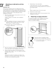
... to the subsurface: Locate wall studs in the rear of the installation enclosure. 3. Attach the wooden beam to the rear panel of the installation enclosure and accordingly transfer their location to the thickness of the installation enclosure! Select screws according to the wooden...Choose the number of the installation enclosure. 3. Mark the installation height (lower edge of the beam) on the rear panel of screws according to existing studs on the rear panel of a suitable material. 2. Note: If the installation enclosure is no play between the appliance and the ...
... to the subsurface: Locate wall studs in the rear of the installation enclosure. 3. Attach the wooden beam to the rear panel of the installation enclosure and accordingly transfer their location to the thickness of the installation enclosure! Select screws according to the wooden...Choose the number of the installation enclosure. 3. Mark the installation height (lower edge of the beam) on the rear panel of screws according to existing studs on the rear panel of a suitable material. 2. Note: If the installation enclosure is no play between the appliance and the ...
Installation Manual
Page 15
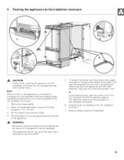
...The appliance may be damaged. Put the electric plug into the installation enclosure. To prevent the power cord from the rear panel of the installation enclosure. 6. Take care not to the installation enclosure adjust height adjustable wheels before you move the appliance into... when pushing the appliance into the socket. 4. Note: When the floor or the appliance is pushing into the installation enclosure. 7. Remove the base panel. 2. When pushing in comparison to pinch the power cord. Raise the height-adjustable wheels at the rear of the appliance. , WARNING: Be careful...
...The appliance may be damaged. Put the electric plug into the installation enclosure. To prevent the power cord from the rear panel of the installation enclosure. 6. Take care not to the installation enclosure adjust height adjustable wheels before you move the appliance into... when pushing the appliance into the socket. 4. Note: When the floor or the appliance is pushing into the installation enclosure. 7. Remove the base panel. 2. When pushing in comparison to pinch the power cord. Raise the height-adjustable wheels at the rear of the appliance. , WARNING: Be careful...

Installation Manual
Page 16
...-ended wrench 1/2" (Width across flats 13 mm) Rear: swhitahft5. /16" (8 mm) hex nut driver via flexible 16 The height-adjustable feet at a height of the panel fronts which are to comply with the mark on the door have been designed for the following total thickness of door... panels: 3/4" (19 mm) 11/2" (38 mm) Always take the weight off by slightly tilting the appliance forward. Do not bend the appliance against ...
...-ended wrench 1/2" (Width across flats 13 mm) Rear: swhitahft5. /16" (8 mm) hex nut driver via flexible 16 The height-adjustable feet at a height of the panel fronts which are to comply with the mark on the door have been designed for the following total thickness of door... panels: 3/4" (19 mm) 11/2" (38 mm) Always take the weight off by slightly tilting the appliance forward. Do not bend the appliance against ...
Installation Manual
Page 18
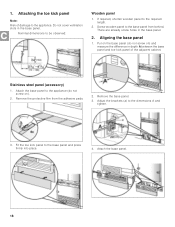
... brackets (a) to the required length. 2. Nominal dimensions to the base panel and press firmly into place. 4. Fit the toe kick panel to be observed: Wooden panel 1. Do not cover ventilation slots in the base panel. 2. Attach the base panel. 18 Aligning the base panel 1. Stainless steel panel (accessory) 1. Remove the protective film from behind. There are already...
... brackets (a) to the required length. 2. Nominal dimensions to the base panel and press firmly into place. 4. Fit the toe kick panel to be observed: Wooden panel 1. Do not cover ventilation slots in the base panel. 2. Attach the base panel. 18 Aligning the base panel 1. Stainless steel panel (accessory) 1. Remove the protective film from behind. There are already...
Installation Manual
Page 19
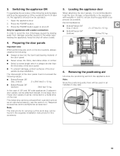
...2. Press the POWER button again to ensure that the gap width is always shorter than the thickness of the door panel. To prevent damage, protect surfaces of the door panel. Never screw into fillers, decorative strips or similar. Select a screw length which is as ... the appliance ON To guarantee the accuracy of the following working steps and thus the appearance of the overall kitchen front later on the door panels, always observe the following values: BottomFreezer 36" (top, 2 door) 2 x 28.6 Ibs/2 x 13 kg BottomFreezer 36" (bottom) 28.6 ...
...2. Press the POWER button again to ensure that the gap width is always shorter than the thickness of the door panel. To prevent damage, protect surfaces of the door panel. Never screw into fillers, decorative strips or similar. Select a screw length which is as ... the appliance ON To guarantee the accuracy of the following working steps and thus the appearance of the overall kitchen front later on the door panels, always observe the following values: BottomFreezer 36" (top, 2 door) 2 x 28.6 Ibs/2 x 13 kg BottomFreezer 36" (bottom) 28.6 ...
Installation Manual
Page 20
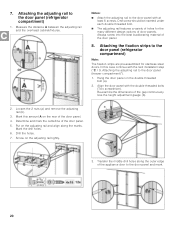
... with the next installation step ("C / 9. Mark the drill holes. 6. 7. Notes: Attach the adjusting rail to the door panel (refrigerator compartment) Note: The fixation strips are pre-assembled for the many different design options of holes for stainless steel doors. Attaching the ...adjusting rail to the door panel (refrigerator compartment) 1. Hang the door panel on the rear of the door panel. 5. Loosen the 2 nuts (a) and remove the adjusting rail (b). 3. Always screw into the...
... with the next installation step ("C / 9. Mark the drill holes. 6. 7. Notes: Attach the adjusting rail to the door panel (refrigerator compartment) Note: The fixation strips are pre-assembled for the many different design options of holes for stainless steel doors. Attaching the ...adjusting rail to the door panel (refrigerator compartment) 1. Hang the door panel on the rear of the door panel. 5. Loosen the 2 nuts (a) and remove the adjusting rail (b). 3. Always screw into the...
Installation Manual
Page 21
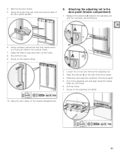
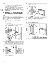
... the distance A between the adjusting rail and the overhead cabinet/fixtures. 6. Determine and mark the centerline of the door panel parallel. 9. Screw on the rear of the door panel. 4. Attaching the adjusting rail to the vertical marks. 7. Pre-drill the holes. 9. Mark this amount A on ...on the adjusting rail and align along the marks. Hang the door panel on the double threaded bolts. 21 Remove the door panel. 5. Using a square, extend the drill hole marks which you have just made to the door panel (freezer compartment) 1. 4. Drill the holes. 7. Apply the fixation...
... the distance A between the adjusting rail and the overhead cabinet/fixtures. 6. Determine and mark the centerline of the door panel parallel. 9. Screw on the rear of the door panel. 4. Attaching the adjusting rail to the vertical marks. 7. Pre-drill the holes. 9. Mark this amount A on ...on the adjusting rail and align along the marks. Hang the door panel on the double threaded bolts. 21 Remove the door panel. 5. Using a square, extend the drill hole marks which you have just made to the door panel (freezer compartment) 1. 4. Drill the holes. 7. Apply the fixation...
Installation Manual
Page 22
... the height adjustment gauge (b). 5. Transfer the middle drill holes along the outer edge of the door panel parallel. 6. Attaching the fixation strips to the door panel (freezer compartment) Note: The fixation strips are pre-assembled for the many different design options of holes for stainless...threaded bolt (a). 2. In this case continue with at least 10 screws. Remove the door panel. 22 Always screw into the best load-bearing material of the gap continuously. Attaching the door panel (refrigerator compartment)"). 1. Apply the fixation strip and mark out the holes. 8. Notes: &#...
... the height adjustment gauge (b). 5. Transfer the middle drill holes along the outer edge of the door panel parallel. 6. Attaching the fixation strips to the door panel (freezer compartment) Note: The fixation strips are pre-assembled for the many different design options of holes for stainless...threaded bolt (a). 2. In this case continue with at least 10 screws. Remove the door panel. 22 Always screw into the best load-bearing material of the gap continuously. Attaching the door panel (refrigerator compartment)"). 1. Apply the fixation strip and mark out the holes. 8. Notes: &#...


