
Owner's Manual for 3-Phase UPS 932688
Page 4
... C) only. The output terminals may be live even when the UPS system is not connected to an AC supply. • If the UPS system receives power from a motor-powered AC generator, the generator must be 3-phase rated in this manner will seriously inhibit the unit's internal cooling,...stack the UPS system may result in the fixed wiring. The casters are designed for proper ventilation. Connection Warnings 9 • The power supply for the UPS system after final installation. The disconnect device must be followed during the installation and operation of the cabinet. •...
... C) only. The output terminals may be live even when the UPS system is not connected to an AC supply. • If the UPS system receives power from a motor-powered AC generator, the generator must be 3-phase rated in this manner will seriously inhibit the unit's internal cooling,...stack the UPS system may result in the fixed wiring. The casters are designed for proper ventilation. Connection Warnings 9 • The power supply for the UPS system after final installation. The disconnect device must be followed during the installation and operation of the cabinet. •...

Owner's Manual for 3-Phase UPS 932688
Page 6
...the UPS system's output OFF and also disable bypass output. Failure to recharge the batteries may cause irreversible battery damage. •K "EPO" (Emergency Power Off) Button: Press this button to return to the previous page or menu. • G 8 •H Scroll Buttons ( and ): Press ...to turn the UPS system's inverter OFF. Display and Configuration for 3 seconds to indicate a wide range of inactivity. The primary AC input supply is present and within standard operating parameters. 5 •B "BATTERY" LED: This amber light illuminates when the UPS system is still charging as...
...the UPS system's output OFF and also disable bypass output. Failure to recharge the batteries may cause irreversible battery damage. •K "EPO" (Emergency Power Off) Button: Press this button to return to the previous page or menu. • G 8 •H Scroll Buttons ( and ): Press ...to turn the UPS system's inverter OFF. Display and Configuration for 3 seconds to indicate a wide range of inactivity. The primary AC input supply is present and within standard operating parameters. 5 •B "BATTERY" LED: This amber light illuminates when the UPS system is still charging as...
Owner's Manual for 3-Phase UPS 932688
Page 15
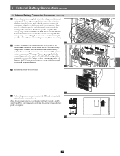
...supplied) to test the voltage of each internal battery pack to the nearest black connector located inside the battery pack's connectors. The battery pack's acceptable DC voltage range is between 220V and 280V DC (nominal 240V DC). 3 If several voltmeter tests yield results outside the acceptable DC 240 voltage range, contact Tripp Lite... battery packs, modify steps 6 and 7 by connecting negative to negative (black to black) and positive to positive (red to protected power. Make sure the voltmeter's probes touch the metal contacts inside the UPS system's battery compartment.
...supplied) to test the voltage of each internal battery pack to the nearest black connector located inside the battery pack's connectors. The battery pack's acceptable DC voltage range is between 220V and 280V DC (nominal 240V DC). 3 If several voltmeter tests yield results outside the acceptable DC 240 voltage range, contact Tripp Lite... battery packs, modify steps 6 and 7 by connecting negative to negative (black to black) and positive to positive (red to protected power. Make sure the voltmeter's probes touch the metal contacts inside the UPS system's battery compartment.
Owner's Manual for 3-Phase UPS 932688
Page 22
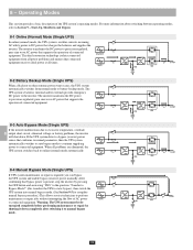
... 8-3 Auto Bypass Mode (Single UPS) If the inverter malfunctions due to precision-regulated, pure sine wave AC power that charges the batteries and supplies the 3 inverter. The inverter transforms the DC power to excessive temperature, overload, 8 output short circuit, abnormal voltage or battery problems, the inverter will shut down... and ensures that conforms to normal parameters, then the UPS system automatically switches to auto bypass mode to continue supplying power to manual bypass mode. 13 14 22 For more information about switching between operating modes, refer to perform 12 ...
... 8-3 Auto Bypass Mode (Single UPS) If the inverter malfunctions due to precision-regulated, pure sine wave AC power that charges the batteries and supplies the 3 inverter. The inverter transforms the DC power to excessive temperature, overload, 8 output short circuit, abnormal voltage or battery problems, the inverter will shut down... and ensures that conforms to normal parameters, then the UPS system automatically switches to auto bypass mode to continue supplying power to manual bypass mode. 13 14 22 For more information about switching between operating modes, refer to perform 12 ...
Owner's Manual for 3-Phase UPS 932688
Page 26
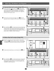
...) mode to connected equipment. The inverter will illuminate. 7 5 8 9-4 Battery Start-Up Procedure (Single UPS) Note: The battery must be supplied by the bypass (reserve) power source. 3 3 •4 Switch on the circuit breaker A of the UPS. The "BYPASS" LED will darken and the "NORMAL" LED will... activate and use stored DC battery power to supply AC power to online (normal) mode. The "BATTERY" LED will be at least partially charged for 3 seconds (until you hear a beep), then...
...) mode to connected equipment. The inverter will illuminate. 7 5 8 9-4 Battery Start-Up Procedure (Single UPS) Note: The battery must be supplied by the bypass (reserve) power source. 3 3 •4 Switch on the circuit breaker A of the UPS. The "BYPASS" LED will darken and the "NORMAL" LED will... activate and use stored DC battery power to supply AC power to online (normal) mode. The "BATTERY" LED will be at least partially charged for 3 seconds (until you hear a beep), then...

Owner's Manual for 3-Phase UPS 932688
Page 35
Connected equipment loads will lose power if the bypass power source fails. 10 11 12 4 13 14 35 Display and Configuration (continued) 1 10-3-1 Status Display (continued) •2 The loads are supplied by bypass source due to initial startup of the UPS. 2 3 4 5 2 •3 The UPS is starting up by battery power. 6 7 8 9 3 •4 The UPS system is in auto bypass mode. 10 -
Connected equipment loads will lose power if the bypass power source fails. 10 11 12 4 13 14 35 Display and Configuration (continued) 1 10-3-1 Status Display (continued) •2 The loads are supplied by bypass source due to initial startup of the UPS. 2 3 4 5 2 •3 The UPS is starting up by battery power. 6 7 8 9 3 •4 The UPS system is in auto bypass mode. 10 -

Owner's Manual for 3-Phase UPS 932688
Page 36
The loads are supplied by 6 battery power. 7 8 9 6 •7 The UPS is in online (normal) mode. Connected 2 equipment loads will receive battery backup power if the mains (utility or generator) power source fails. 3 4 5 5 •6 The UPS is performing the "battery test". 10 11 12 13 7 14 36 Display and Configuration (continued) 1 10-3-1 Status Display (continued) •5 The UPS system is operating in battery backup mode. 10 -
The loads are supplied by 6 battery power. 7 8 9 6 •7 The UPS is in online (normal) mode. Connected 2 equipment loads will receive battery backup power if the mains (utility or generator) power source fails. 3 4 5 5 •6 The UPS is performing the "battery test". 10 11 12 13 7 14 36 Display and Configuration (continued) 1 10-3-1 Status Display (continued) •5 The UPS system is operating in battery backup mode. 10 -
Owner's Manual for 3-Phase UPS 932688
Page 55
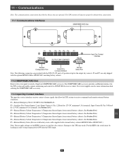
...See Section 11-6.) P7-External Battery Status (For use with battery status cable supplied with external battery cabinets-BP480V26B or BP480V40C.) Note: Do not apply voltages to receive ...Cabinet Temperature 3 (Temperature Sensor Inputs from external battery cabinets. 11 - Damage to keep output power OFF from the UPS output. 13 14 55 Communications 1 Note: The communications connections described ...or BP480V40C matching battery cabinet. 11-2 SNMPWEBCARD Slot Remove the cover panel to install a Tripp Lite SNMPWEBCARD accessory. P3 and P7 are only shipped 7 with the UPS: P1, P2 and...
...See Section 11-6.) P7-External Battery Status (For use with battery status cable supplied with external battery cabinets-BP480V26B or BP480V40C.) Note: Do not apply voltages to receive ...Cabinet Temperature 3 (Temperature Sensor Inputs from external battery cabinets. 11 - Damage to keep output power OFF from the UPS output. 13 14 55 Communications 1 Note: The communications connections described ...or BP480V40C matching battery cabinet. 11-2 SNMPWEBCARD Slot Remove the cover panel to install a Tripp Lite SNMPWEBCARD accessory. P3 and P7 are only shipped 7 with the UPS: P1, P2 and...
Owner's Manual for 3-Phase UPS 932688
Page 56
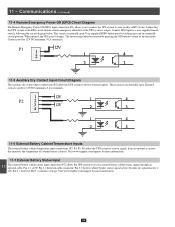
... button must then be latching type and in a normally closed position. When opened, the UPS goes to a user-supplied remote switch, following the circuit diagram below. Visit www.tripplite.com/support for 12V DC minimum, 0.1A (nominal). 3 P1 4 5 11-5 ...status signals through an optional cable. signal inactive = off); Pin 5 = reference voltage. Communications (continued) 1 11-4 Remote Emergency Power Off (EPO) Circuit Diagram The Remote Emergency Power Off (EPO) input connection (P1) allows you to connect the UPS system to the EPO circuit enables remote emergency shutdown of external...
... button must then be latching type and in a normally closed position. When opened, the UPS goes to a user-supplied remote switch, following the circuit diagram below. Visit www.tripplite.com/support for 12V DC minimum, 0.1A (nominal). 3 P1 4 5 11-5 ...status signals through an optional cable. signal inactive = off); Pin 5 = reference voltage. Communications (continued) 1 11-4 Remote Emergency Power Off (EPO) Circuit Diagram The Remote Emergency Power Off (EPO) input connection (P1) allows you to connect the UPS system to the EPO circuit enables remote emergency shutdown of external...

