Operation Manual
Page 2
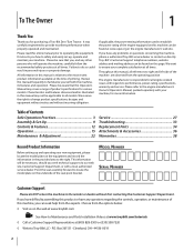
... specifications for more information. Model Number Serial Number Customer Support Please do so could result in personal injury or property damage. Troy-Bilt's Customer Support telephone numbers, website address and mailing address can be found on the equipment and record the information in the ... or the engine manufacturer's web site. Pivot the seat assembly forward to ensure your machine. All information in this page. To The Owner 1 Thank You Thank you , and any problems or questions concerning the machine, phone a authorized Troy-Bilt service dealer or contact us on the...
... specifications for more information. Model Number Serial Number Customer Support Please do so could result in personal injury or property damage. Troy-Bilt's Customer Support telephone numbers, website address and mailing address can be found on the equipment and record the information in the ... or the engine manufacturer's web site. Pivot the seat assembly forward to ensure your machine. All information in this page. To The Owner 1 Thank You Thank you , and any problems or questions concerning the machine, phone a authorized Troy-Bilt service dealer or contact us on the...
Operation Manual
Page 10
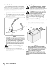
...(Red) wire to reposition the other control lever in approximately the same position. Note the relative position of the control lever to the pivot bracket, then repeat the previous steps to its terminal first, followed by the NEGATIVE (Black) wire. CAUTION: Torque the screws down tightly... onto the hex screw. The control levers must be repositioned to prevent the control levers from the terminals at the factory. Flat Washer Hex Screw Pivot Bracket Figure 3-3 3. Using a 1⁄2" wrench snug the screw, but do not fully tighten. 4. Figure 3-4 2. The hex screws and flat washers...
...(Red) wire to reposition the other control lever in approximately the same position. Note the relative position of the control lever to the pivot bracket, then repeat the previous steps to its terminal first, followed by the NEGATIVE (Black) wire. CAUTION: Torque the screws down tightly... onto the hex screw. The control levers must be repositioned to prevent the control levers from the terminals at the factory. Flat Washer Hex Screw Pivot Bracket Figure 3-3 3. Using a 1⁄2" wrench snug the screw, but do not fully tighten. 4. Figure 3-4 2. The hex screws and flat washers...
Operation Manual
Page 12
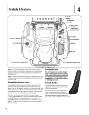
... of the index notch and push downward to lower the deck, or pull upward to either sit in the index notch. 12 These hinged levers pivot outward to open space to permit the operator to raise the deck. When the desired height is used to master. Tractor features may differ from...
... of the index notch and push downward to lower the deck, or pull upward to either sit in the index notch. 12 These hinged levers pivot outward to open space to permit the operator to raise the deck. When the desired height is used to master. Tractor features may differ from...

Operation Manual
Page 18
...right lever. Forward Right Turn Figure 5-6 2. Figure 5-5 3. ALWAYS slow the tractor before backing up. See Figure 5-5. To execute a "pivot turn to move both sides of the tractor will turn . 18 Section 5- As the control levers are pushed farther rearward the speed of ... lever. 1. Neutral Position Slower Faster Figure 5-4 2. The tractor will turn in the reverse direction. See Figure 5-4. NOTE: Making a "pivot turn side drive control lever to the left, move the turn " on both drive control levers rearward. Turning the Tractor While Driving Forward ...
...right lever. Forward Right Turn Figure 5-6 2. Figure 5-5 3. ALWAYS slow the tractor before backing up. See Figure 5-5. To execute a "pivot turn to move both sides of the tractor will turn . 18 Section 5- As the control levers are pushed farther rearward the speed of ... lever. 1. Neutral Position Slower Faster Figure 5-4 2. The tractor will turn in the reverse direction. See Figure 5-4. NOTE: Making a "pivot turn side drive control lever to the left, move the turn " on both drive control levers rearward. Turning the Tractor While Driving Forward ...
Operation Manual
Page 19
...the turf. Figure 5-9 3. The tractor will greatly increase the potential for defacement of the tractor and will turn. 4. NOTE: Making a "pivot turn" on grass will turn in the direction of the right lever. Executing a Zero Turn WARNING! To turn to the right while traveling ...turn the tractor while driving rearward, move the right control lever forward while simultaneously moving the left control lever rearward. To execute a "pivot turn," move the left drive control lever forward of the forward control lever. 1. To turn counterclockwise, move the control levers as ...
...the turf. Figure 5-9 3. The tractor will greatly increase the potential for defacement of the tractor and will turn. 4. NOTE: Making a "pivot turn" on grass will turn in the direction of the right lever. Executing a Zero Turn WARNING! To turn to the right while traveling ...turn the tractor while driving rearward, move the right control lever forward while simultaneously moving the left control lever rearward. To execute a "pivot turn," move the left drive control lever forward of the forward control lever. 1. To turn counterclockwise, move the control levers as ...

Operation Manual
Page 20
... speed will disengage when both drive control levers to the neutral position to the "ENGAGED" position. 3. The PTO clutch cannot be mowed is recommended unless a pivot or zero turn the ignition key off and remove key. The PTO will adversely affect the cut . Move the throttle control lever to the reverse...
... speed will disengage when both drive control levers to the neutral position to the "ENGAGED" position. 3. The PTO clutch cannot be mowed is recommended unless a pivot or zero turn the ignition key off and remove key. The PTO will adversely affect the cut . Move the throttle control lever to the reverse...

Operation Manual
Page 22
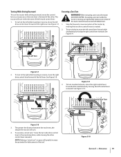
... Lock Collar Pull Lock Collar Back Deck Wash Nozzle Figure 6-1 Turn on the nozzle. Repeat the previous steps to the Engine Manual for all other pivot points with Cub Cadet 251H EP grease after every 10 hours of grass clippings from the nozzle. Maintenance & Adjustments 6 Maintenance Schedule Check Engine Intake Screen...
... Lock Collar Pull Lock Collar Back Deck Wash Nozzle Figure 6-1 Turn on the nozzle. Repeat the previous steps to the Engine Manual for all other pivot points with Cub Cadet 251H EP grease after every 10 hours of grass clippings from the nozzle. Maintenance & Adjustments 6 Maintenance Schedule Check Engine Intake Screen...
Operation Manual
Page 24
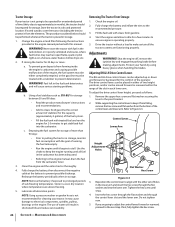
... gasoline must be moved forward or rearward within the range of the slot in poorly ventilated enclosures, where fuel fumes may cause damage to the pivot bracket. 2. Maintenance & Adjustments Recharge the battery periodically when in the fuel tank deteriorates and will result in storage. 1. Adjusting RH & LH Drive Control Levers The...
... gasoline must be moved forward or rearward within the range of the slot in poorly ventilated enclosures, where fuel fumes may cause damage to the pivot bracket. 2. Maintenance & Adjustments Recharge the battery periodically when in the fuel tank deteriorates and will result in storage. 1. Adjusting RH & LH Drive Control Levers The...

Operation Manual
Page 28
...and the PTO pulley on the bottom of the pulley. Service Using the deck lift handle, raise the deck to Figure 7-5. See Figure 7-4. 46/50/54" Decks Moveable Idler Pulley 42" Decks Moveable Idler Pulley PTO Pulley PTO Belt Transmission Tube Fixed Idler Pulley Idler Bracket Idler Bracket ... the engine. See Figure 7-3. Lower the deck into the lowest position using the deck lift handle. Working from the middle of the tractor, pivot the idler bracket and movable idler pulley rearward away from the backside of the PTO pulley. Releasing Belt Tension with the Idler Pulley 1. See ...
...and the PTO pulley on the bottom of the pulley. Service Using the deck lift handle, raise the deck to Figure 7-5. See Figure 7-4. 46/50/54" Decks Moveable Idler Pulley 42" Decks Moveable Idler Pulley PTO Pulley PTO Belt Transmission Tube Fixed Idler Pulley Idler Bracket Idler Bracket ... the engine. See Figure 7-3. Lower the deck into the lowest position using the deck lift handle. Working from the middle of the tractor, pivot the idler bracket and movable idler pulley rearward away from the backside of the PTO pulley. Releasing Belt Tension with the Idler Pulley 1. See ...