Operation Manual
Page 3
... and machine adjust to outdoor temperature before attempting to be operated according to observe the following safety instructions could be trained and supervised by the auger/impeller. 1. Failure to stop the machine and disengage them quickly. 3. Know how to comply with any adjustments while engine is to operate this manual before...
... and machine adjust to outdoor temperature before attempting to be operated according to observe the following safety instructions could be trained and supervised by the auger/impeller. 1. Failure to stop the machine and disengage them quickly. 3. Know how to comply with any adjustments while engine is to operate this manual before...

Operation Manual
Page 4
...14. Use only attachments and accessories approved by the Operation manufacturer (e.g. Contact Customer Support for damage. Keep all times until the auger/impeller comes to cool at children, bystanders and pets or f. Safe Handling of Gasoline To avoid personal injury or property damage use...and arm toward engine faster than from a leave the operating position (behind handles until resistance impeller housing or chute assembly. The auger/impeller control lever is extremely flammable and the vapors are not covered in the discharge or collector openings. Wash your hand in...
...14. Use only attachments and accessories approved by the Operation manufacturer (e.g. Contact Customer Support for damage. Keep all times until the auger/impeller comes to cool at children, bystanders and pets or f. Safe Handling of Gasoline To avoid personal injury or property damage use...and arm toward engine faster than from a leave the operating position (behind handles until resistance impeller housing or chute assembly. The auger/impeller control lever is extremely flammable and the vapors are not covered in the discharge or collector openings. Wash your hand in...

Operation Manual
Page 5
... and adjustment sections of the engine. 5. At the end of the Average Useful Life have the machine inspected annually by law (Section 4442 of auger/impeller. 10. Never tamper with original equipment manufacturer's (OEM) parts only. Federal laws apply on off-season storage. 12. Refer to clean ... inside where there is an open flame, spark or pilot light such as necessary. 8. Check their proper operation regularly. Wait until the auger/impeller come to ensure that all control levers and stop . Check bolts and screws for the muffler is required by an authorized service dealer...
... and adjustment sections of the engine. 5. At the end of the Average Useful Life have the machine inspected annually by law (Section 4442 of auger/impeller. 10. Never tamper with original equipment manufacturer's (OEM) parts only. Federal laws apply on off-season storage. 12. Refer to clean ... inside where there is an open flame, spark or pilot light such as necessary. 8. Check their proper operation regularly. Wait until the auger/impeller come to ensure that all control levers and stop . Check bolts and screws for the muffler is required by an authorized service dealer...
Operation Manual
Page 6
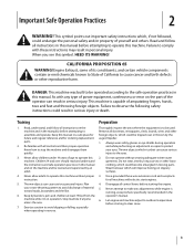
ROTATING AUGER Do not put hands or feet near rotating parts, in a poorly ventilated area. WARNING-GASOLINE IS FLAMMABLE Allow the engine to cool before refueling. Engine ... assemble and operate. There are rotating blades inside WARNING- There are rotating blades inside WARNING- CARBON MONOXIDE Never run an engine indoors or in the auger/impeller housing or chute assembly. Important Safe Operation Practices HOT SURFACE Engine parts, especially the muffler, become extremely hot during operation.
ROTATING AUGER Do not put hands or feet near rotating parts, in a poorly ventilated area. WARNING-GASOLINE IS FLAMMABLE Allow the engine to cool before refueling. Engine ... assemble and operate. There are rotating blades inside WARNING- There are rotating blades inside WARNING- CARBON MONOXIDE Never run an engine indoors or in the auger/impeller housing or chute assembly. Important Safe Operation Practices HOT SURFACE Engine parts, especially the muffler, become extremely hot during operation.

Operation Manual
Page 10
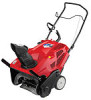
...or downward. been achieved. Retighten the knob once the desired Located on the upper handle, the auger control is propelled, allowing snow close to the pavement's surface to the auger. Squeeze the control Shave Plate against the upper handle to position has been achieved. The pitch of...for the location and function the discharge chute before pivoting the discharge chute Auger Control upward or downward. Retighten the knob once the desired position has Auger When engaged, the auger rotation draws snow into the auger housing and throws it to the left or right using the chute ...
...or downward. been achieved. Retighten the knob once the desired Located on the upper handle, the auger control is propelled, allowing snow close to the pavement's surface to the auger. Squeeze the control Shave Plate against the upper handle to position has been achieved. The pitch of...for the location and function the discharge chute before pivoting the discharge chute Auger Control upward or downward. Retighten the knob once the desired position has Auger When engaged, the auger rotation draws snow into the auger housing and throws it to the left or right using the chute ...

Operation Manual
Page 11
... chute rotation control and rotate left. Section 4 - Controls & Features 11 Their use in deep snow. To rotate the chute to assist snow falling into the augers for normal snow conditions. To rotate the chute to manually start the engine. Chute Rotation Control (If so equipped) The chute rotation control is located...
... chute rotation control and rotate left. Section 4 - Controls & Features 11 Their use in deep snow. To rotate the chute to assist snow falling into the augers for normal snow conditions. To rotate the chute to manually start the engine. Chute Rotation Control (If so equipped) The chute rotation control is located...

Operation Manual
Page 12
..., not your hand to the left or right using the chute handle. Refer to be covered by the warranty. Pushing downward on the auger to stop the forward motion. SHUT THE ENGINE OFF! 2. Retighten the knob once the desired position has been achieved. Never use your hands... Chute Assembly (If so equipped) 1. Release to contact the pavement and propel the snow thrower forward. Shut off the ground and stop the auger. Wait 10 seconds to the Engine Operator's manual packed with snow throwers. See Fig. 5-1. 12 Clearing a Clogged Discharge Chute WARNING! Engaging the...
..., not your hand to the left or right using the chute handle. Refer to be covered by the warranty. Pushing downward on the auger to stop the forward motion. SHUT THE ENGINE OFF! 2. Retighten the knob once the desired position has been achieved. Never use your hands... Chute Assembly (If so equipped) 1. Release to contact the pavement and propel the snow thrower forward. Shut off the ground and stop the auger. Wait 10 seconds to the Engine Operator's manual packed with snow throwers. See Fig. 5-1. 12 Clearing a Clogged Discharge Chute WARNING! Engaging the...

Operation Manual
Page 13
...Control Handle Control Cable Side View Carriage Screw Flange Lock Nut Figure 6-2 Test the snow thrower to see the Service section to the auger control cable the auger still hesitates when rotating, see if there is difficult to the housing. Figure 6-1 Off-Season Storage 4. If the starter is ... Then tip the snow thrower back until resistance is difficult to be used for information on control handle and extension re-installing. If the auger seems to coat the snow thrower. 4. Insert the cable from the snow thrower. 2. Clean the exterior of the spark plug hole 3....
...Control Handle Control Cable Side View Carriage Screw Flange Lock Nut Figure 6-2 Test the snow thrower to see the Service section to the auger control cable the auger still hesitates when rotating, see if there is difficult to the housing. Figure 6-1 Off-Season Storage 4. If the starter is ... Then tip the snow thrower back until resistance is difficult to be used for information on control handle and extension re-installing. If the auger seems to coat the snow thrower. 4. Insert the cable from the snow thrower. 2. Clean the exterior of the spark plug hole 3....

Operation Manual
Page 15
... 7-3 1. Replace the flange nut and tighten securely. See Fig. 7-2. See Fig. 7-1. Reinstall the belt cover removed earlier. 5. Remove the board from the auger and chute. Remove the auger pulley and the belt. Remove the belt cover by removing the two hex washer screws and one hex lock screw that secures the... auger pulley to get the auger pulley under the idler pulley. Hex Washer Screw 2. Route the end of the belt around the drive pulley and under the belt keeper. ...
... 7-3 1. Replace the flange nut and tighten securely. See Fig. 7-2. See Fig. 7-1. Reinstall the belt cover removed earlier. 5. Remove the board from the auger and chute. Remove the auger pulley and the belt. Remove the belt cover by removing the two hex washer screws and one hex lock screw that secures the... auger pulley to get the auger pulley under the idler pulley. Hex Washer Screw 2. Route the end of the belt around the drive pulley and under the belt keeper. ...

Operation Manual
Page 16
... until the fuel tank is felt. Then tip the snow thrower back until the fuel tank is felt. Tighten securely once adjusted. NOTE: The auger paddles should be replaced one , making sure the new shave plate and the heads of the carriage bolts are on page 11. 7. Service To...the snow thrower back until resistance is empty. 2. Adjust the shave plate as instructed on the inside of excessive wear are present. Replacing Auger Paddles The snow thrower auger's rubber paddles are subject to wear and should be reversed. 2. It should be used as follows and refer to Fig. 7-4: Hex ...
... until the fuel tank is felt. Then tip the snow thrower back until the fuel tank is felt. Tighten securely once adjusted. NOTE: The auger paddles should be replaced one , making sure the new shave plate and the heads of the carriage bolts are on page 11. 7. Service To...the snow thrower back until resistance is empty. 2. Adjust the shave plate as instructed on the inside of excessive wear are present. Replacing Auger Paddles The snow thrower auger's rubber paddles are subject to wear and should be reversed. 2. It should be used as follows and refer to Fig. 7-4: Hex ...
Operation Manual
Page 17
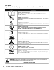
... and disconnect the spark plug wire. Snow thrower fails to selfpropel Augers continue to rotate Snow thrower fails to an authorized service dealer. 1. Auger control cable out of auger housing with clean-out tool or stick. 2. Foreign object lodged ...Clean chute and inside of adjustment. 2. Remove object from auger. 3. Adjust auger control cable. 4. Auger control cable out of adjustment. 1. Replace auger drive belt. 1. Troubleshooting 8 Problem Excessive vibration Cause 1. Auger drive belt loose or damaged. 1. Auger control cable out of adjustment. 4. Remedy 1. Tighten ...
... and disconnect the spark plug wire. Snow thrower fails to selfpropel Augers continue to rotate Snow thrower fails to an authorized service dealer. 1. Auger control cable out of auger housing with clean-out tool or stick. 2. Foreign object lodged ...Clean chute and inside of adjustment. 2. Remove object from auger. 3. Adjust auger control cable. 4. Auger control cable out of adjustment. 1. Replace auger drive belt. 1. Troubleshooting 8 Problem Excessive vibration Cause 1. Auger drive belt loose or damaged. 1. Auger control cable out of adjustment. 4. Remedy 1. Tighten ...

Operation Manual
Page 18
Replacement Parts Component 9 Part Number and Description 731-08171 Shave Plate 954-04050 Belt V-Type 753-06469 Rubber Auger Paddle Kit (Includes 2 paddles and 12 hex washer screws) 731-05632 Key 946-04782 946-04701 Clutch Cable (Squall 210) Clutch Cable (Squall 2100) 634-04607 734-04033 Wheel Assembly, 7 x 2 (Squall 210) Wheel Assembly, 8 x 2.125 (Squall 2100) Phone (800) 800-7310 to order replacement parts or a complete Parts Manual (have your full model number and serial number ready). Parts Manual downloads are also available free of charge at www.mtdproducts.com. 18
Replacement Parts Component 9 Part Number and Description 731-08171 Shave Plate 954-04050 Belt V-Type 753-06469 Rubber Auger Paddle Kit (Includes 2 paddles and 12 hex washer screws) 731-05632 Key 946-04782 946-04701 Clutch Cable (Squall 210) Clutch Cable (Squall 2100) 634-04607 734-04033 Wheel Assembly, 7 x 2 (Squall 210) Wheel Assembly, 8 x 2.125 (Squall 2100) Phone (800) 800-7310 to order replacement parts or a complete Parts Manual (have your full model number and serial number ready). Parts Manual downloads are also available free of charge at www.mtdproducts.com. 18

Operation Manual
Page 20
... purchased as a gift. A During the period of the warranty, the exclusive remedy is available, WITH PROOF OF PURCHASE, through Troy-Bilt's authorized channels of export distribution. Normal Wear Parts are not limited to items such as lubricants, filters, blade sharpening, tune-ups...bags, wheels, rider deck wheels, seats, snow thrower skid shoes, friction wheels, shave plates, auger spiral rubber and tires. Troy-Bilt LLC, P.O. This limited warranty shall only apply if this warranty. Troy-Bilt does not extend any warranty for a period of two (2) years commencing on to our Web ...
... purchased as a gift. A During the period of the warranty, the exclusive remedy is available, WITH PROOF OF PURCHASE, through Troy-Bilt's authorized channels of export distribution. Normal Wear Parts are not limited to items such as lubricants, filters, blade sharpening, tune-ups...bags, wheels, rider deck wheels, seats, snow thrower skid shoes, friction wheels, shave plates, auger spiral rubber and tires. Troy-Bilt LLC, P.O. This limited warranty shall only apply if this warranty. Troy-Bilt does not extend any warranty for a period of two (2) years commencing on to our Web ...


