Service Manual
Page 9
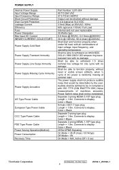
... Power Saving Operation(Method) Power Consumption Recovery Time Part Number: ILIPI-004 90 TO 264 VAC 47.5 TO 63 HERTZ Output can be shorted without reset or visible screen artifacts, when ½ cycle of machines acoustics. Connects to display. Connects to display. Color = Black VESA DPMS Signaling On Mode < 36 W (max...
... Power Saving Operation(Method) Power Consumption Recovery Time Part Number: ILIPI-004 90 TO 264 VAC 47.5 TO 63 HERTZ Output can be shorted without reset or visible screen artifacts, when ½ cycle of machines acoustics. Connects to display. Connects to display. Color = Black VESA DPMS Signaling On Mode < 36 W (max...
Service Manual
Page 22
...The frequency of XTAL2 is detected for around 1.5 seconds, IC501 will shut down . U105 #43 outputs reset signal to drive MOSFET U501, U502. U104 #1, #102-#103, #106-#113, #118-#125, ...#128 output LVDS digital data of 8 bit to panel control circuit through sense resistor R509, R511. ViewSonic Corporation Confidential - The output drives, including NDR4, NDRV2, PDRV3, PDRV1 (pins1, 3, 15, 16 respectively), generate...after C109 and C110 filtering, obtain the voltage of VLCD, which are the communications with #16 and #17 of MCU. U105 #14, #36, #37, #38, #39, #40, #41, #42...
...The frequency of XTAL2 is detected for around 1.5 seconds, IC501 will shut down . U105 #43 outputs reset signal to drive MOSFET U501, U502. U104 #1, #102-#103, #106-#113, #118-#125, ...#128 output LVDS digital data of 8 bit to panel control circuit through sense resistor R509, R511. ViewSonic Corporation Confidential - The output drives, including NDR4, NDRV2, PDRV3, PDRV1 (pins1, 3, 15, 16 respectively), generate...after C109 and C110 filtering, obtain the voltage of VLCD, which are the communications with #16 and #17 of MCU. U105 #14, #36, #37, #38, #39, #40, #41, #42...
Service Manual
Page 24
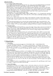
...then U104 will send out High potential, and then LED green on. - Symbol 1,2 +5V (VCC5V) +5.2V output 3,6 GND Ground Description ViewSonic Corporation Confidential - Inner Connector Pin Assignment 6.1 CN501, CN502, CN503, CN504 (Connect to Interface BD) Pin No. High voltage for lamp Low ...T5 (ms) T6 (ms) T7 (ms) 0.1~10 0~10 >200 >100 0~50 0.1~10 >1000 5. The Panel_Vcc, Backlight_En, CLK/DATA output to reset U104, and then monitor goes into AC socket, SMPS starts work and provides U105 and U106 with VCC5V. AC Outlet Pin Assignment 3 1 2 P801 Pin Symbol 1 L 2...
...then U104 will send out High potential, and then LED green on. - Symbol 1,2 +5V (VCC5V) +5.2V output 3,6 GND Ground Description ViewSonic Corporation Confidential - Inner Connector Pin Assignment 6.1 CN501, CN502, CN503, CN504 (Connect to Interface BD) Pin No. High voltage for lamp Low ...T5 (ms) T6 (ms) T7 (ms) 0.1~10 0~10 >200 >100 0~50 0.1~10 >1000 5. The Panel_Vcc, Backlight_En, CLK/DATA output to reset U104, and then monitor goes into AC socket, SMPS starts work and provides U105 and U106 with VCC5V. AC Outlet Pin Assignment 3 1 2 P801 Pin Symbol 1 L 2...
Service Manual
Page 27
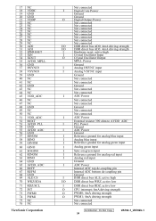
... ADC bottom de-coupling pin Ground I /O DDR direct bus WRZ; Do Not Copy 24 VA702-1_VA702b-1 active high I DDR direct bus ALE; active low I Hardware reset; 17 NC 18 VDDC 19 GND 20 GND 21 VDDP 22 NC 23 NC 24 NC 25 NC 26 NC 27 NC 28 NC 29 NC... 66 REFP 67 REFM 68 GND 69 ALE/CS 70 WRZ/SDA 71 RDZ/SCL 72 INT 73 PWM0 74 PWM1 75 NC 76 NC ViewSonic Corporation Not connected I Digital Core Power Ground Ground O Digital Output Power Not connected Not connected Not connected Not connected Not connected Not connected Not connected...
... ADC bottom de-coupling pin Ground I /O DDR direct bus WRZ; Do Not Copy 24 VA702-1_VA702b-1 active high I DDR direct bus ALE; active low I Hardware reset; 17 NC 18 VDDC 19 GND 20 GND 21 VDDP 22 NC 23 NC 24 NC 25 NC 26 NC 27 NC 28 NC 29 NC... 66 REFP 67 REFM 68 GND 69 ALE/CS 70 WRZ/SDA 71 RDZ/SCL 72 INT 73 PWM0 74 PWM1 75 NC 76 NC ViewSonic Corporation Not connected I Digital Core Power Ground Ground O Digital Output Power Not connected Not connected Not connected Not connected Not connected Not connected Not connected...
Service Manual
Page 29
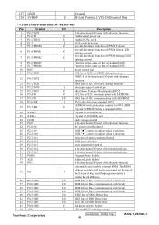
...same as that of standard 8052 Function is the same as that of standard 8052 10 RST I Reset control pin 11 P3.0/RXD SCL line of I2C for EDID, debug function 12 P4.3/INT2 PORT...O Shut Down Volume Mute standard 8052. 16 P3.4/T0 O SCL line of I2C communication with EEPROM 17 P3.5/T1 I/O SDA line of I2C communication with EEPROM 18 P3.6/WR I DVI cable detection standard 8052...control to adjust value to decrease 27 P2.3/A11 Selection of DDR Direct Bus 43 P0.0/AD0 O Hardware reset to Scaler 44 +5V I /O port with internal pull-ups 32 PSEN Program Store Enable 33 ALE Address...
...same as that of standard 8052 Function is the same as that of standard 8052 10 RST I Reset control pin 11 P3.0/RXD SCL line of I2C for EDID, debug function 12 P4.3/INT2 PORT...O Shut Down Volume Mute standard 8052. 16 P3.4/T0 O SCL line of I2C communication with EEPROM 17 P3.5/T1 I/O SDA line of I2C communication with EEPROM 18 P3.6/WR I DVI cable detection standard 8052...control to adjust value to decrease 27 P2.3/A11 Selection of DDR Direct Bus 43 P0.0/AD0 O Hardware reset to Scaler 44 +5V I /O port with internal pull-ups 32 PSEN Program Store Enable 33 ALE Address...


