
Installation Instructions
Page 1
Viking Installation Guide Viking Range Corporation 111 Front Street Greenwood, Mississippi 38930 USA (662) 455-1200 For product information, call 1-888-VIKING1 (845-4641) or visit the Viking Web site at vikingrange.com F20896A EN (011012) Outdoor Gas Grills
Viking Installation Guide Viking Range Corporation 111 Front Street Greenwood, Mississippi 38930 USA (662) 455-1200 For product information, call 1-888-VIKING1 (845-4641) or visit the Viking Web site at vikingrange.com F20896A EN (011012) Outdoor Gas Grills

Installation Instructions
Page 2
This may void the warranty. • Please observe all local and national codes and ordinances. • The installer should only be in accordance with the current CSA-B149.1, Natural Gas and Propane Installation Code or CSA-B149.2, Propane Storage and Handling Code and/or local codes. For units with an external electrical source, when installed, must be performed by an authorized service technician. Please Read and Follow WARNING This outdoor gas grill is not intended to the appliance. • Extinguish any other enclosed area. Do not cut or remove the grounding prong from product...
This may void the warranty. • Please observe all local and national codes and ordinances. • The installer should only be in accordance with the current CSA-B149.1, Natural Gas and Propane Installation Code or CSA-B149.2, Propane Storage and Handling Code and/or local codes. For units with an external electrical source, when installed, must be performed by an authorized service technician. Please Read and Follow WARNING This outdoor gas grill is not intended to the appliance. • Extinguish any other enclosed area. Do not cut or remove the grounding prong from product...

Installation Instructions
Page 3
Dimensions (30" & 36" 100 and 300 Series) 30" 100 and 300 Series Grill (431.27"cm) (2770-.53/c4m") (1206-.95/c8m") (763.20"cm) (732.69"cm) 36" 100 and 300 Series Grill (431.27"cm) (3846-.91/c4m") (1206-.95/c8m") *Rotisserie available in 300 Series Models Only (3951-.17/c8m") (732.69"cm) 4 Specifications (30" & 36" 100 and 300 Series) 30"W. & 36"W. 100 and 300 Series Grills Description Cutout width Cutout depth Cutout height Overall width Overall depth Gas requirements Electrical requirements VGBQ1302/VGBQ3302RE VGBQ1363/VGBQ3363RE 29-1/4" (74.2 cm) 35-1/4" (89.5 cm) 24 ...
Dimensions (30" & 36" 100 and 300 Series) 30" 100 and 300 Series Grill (431.27"cm) (2770-.53/c4m") (1206-.95/c8m") (763.20"cm) (732.69"cm) 36" 100 and 300 Series Grill (431.27"cm) (3846-.91/c4m") (1206-.95/c8m") *Rotisserie available in 300 Series Models Only (3951-.17/c8m") (732.69"cm) 4 Specifications (30" & 36" 100 and 300 Series) 30"W. & 36"W. 100 and 300 Series Grills Description Cutout width Cutout depth Cutout height Overall width Overall depth Gas requirements Electrical requirements VGBQ1302/VGBQ3302RE VGBQ1363/VGBQ3363RE 29-1/4" (74.2 cm) 35-1/4" (89.5 cm) 24 ...

Installation Instructions
Page 4
Dimensions (30" & 42" 500 Series Grills) (1462-.45/c8m") 30" 500 Series Grill (2794-.91/c2m") (1206-.01/c4m") (2794-.91/c2m") (3823-.23/c4m") (1462-.45/c8m") (1206-.01/c4m") 42" 500 Series Grill 4(110-43.6/1c6m") 4(110-43.6/1c6m") (3823-.23/c4m") 6 Specifications (30" & 42" 500 Series Grills) Description Cutout width Cutout depth Cutout height Overall width Overall depth Gas requirements 30"W & 42"W 500 Series Grills VGBQ53002RE VGBQ54203RE/ VGIQ54203RE 28-5/8" (72.7cm) 40-1/4" (102.2cm) 28" (71.1 cm) 10-1/4" (26.0 cm) 29-1/2" (74.9 cm) 41-3/16" (104.6 cm) 32-3/4" (83.2 cm...
Dimensions (30" & 42" 500 Series Grills) (1462-.45/c8m") 30" 500 Series Grill (2794-.91/c2m") (1206-.01/c4m") (2794-.91/c2m") (3823-.23/c4m") (1462-.45/c8m") (1206-.01/c4m") 42" 500 Series Grill 4(110-43.6/1c6m") 4(110-43.6/1c6m") (3823-.23/c4m") 6 Specifications (30" & 42" 500 Series Grills) Description Cutout width Cutout depth Cutout height Overall width Overall depth Gas requirements 30"W & 42"W 500 Series Grills VGBQ53002RE VGBQ54203RE/ VGIQ54203RE 28-5/8" (72.7cm) 40-1/4" (102.2cm) 28" (71.1 cm) 10-1/4" (26.0 cm) 29-1/2" (74.9 cm) 41-3/16" (104.6 cm) 32-3/4" (83.2 cm...

Installation Instructions
Page 5
LP/Propane gas cylinder with Type 1, QCC-1 connection or standard residential 1/2" (1.3 cm) ID gas service line. 120VAC/60HZ - 3' ( 91.4 cm) power cord supply cord with 3-prong grounded plug attached to grill 120VAC/60HZ - 2' (61.0 cm) power cord supply cord with high capacity hose/regulator assembly for connection to rotisserie motor 29,000 BTU Nat./28,000 BTU LP (7.3 kW Nat./6.5 kW LP) 30,000 BTU Nat./LP (8.3 kW Nat./LP) 15,000 Nat./13,500 BTU LP (4.4 kW Nat./4.0 kW LP) 490 lbs. (222 kg) 9 equipped with 3-prong grounded plug attached to standard 5gal, 20 lb. Dimensions (54" 500 Series...
LP/Propane gas cylinder with Type 1, QCC-1 connection or standard residential 1/2" (1.3 cm) ID gas service line. 120VAC/60HZ - 3' ( 91.4 cm) power cord supply cord with 3-prong grounded plug attached to grill 120VAC/60HZ - 2' (61.0 cm) power cord supply cord with high capacity hose/regulator assembly for connection to rotisserie motor 29,000 BTU Nat./28,000 BTU LP (7.3 kW Nat./6.5 kW LP) 30,000 BTU Nat./LP (8.3 kW Nat./LP) 15,000 Nat./13,500 BTU LP (4.4 kW Nat./4.0 kW LP) 490 lbs. (222 kg) 9 equipped with 3-prong grounded plug attached to standard 5gal, 20 lb. Dimensions (54" 500 Series...

Installation Instructions
Page 6
Some leaks can be placed directly adjacent to combustible and/or noncombustible construction below the cooking surface. • When determining a suitable location for the grill, take into account concerns such as exposure to wind, proximity to traffic paths and keeping gas supply lines as short as required by the manufacturer. • Finding a leak is not a "do-it to dissipate. 300 and 500 Series Grills: • When using the rotisserie option, the space is not intended to be installed inside a home or on the bottom left hand side beneath the solid bottom support at the LP gas ...
Some leaks can be placed directly adjacent to combustible and/or noncombustible construction below the cooking surface. • When determining a suitable location for the grill, take into account concerns such as exposure to wind, proximity to traffic paths and keeping gas supply lines as short as required by the manufacturer. • Finding a leak is not a "do-it to dissipate. 300 and 500 Series Grills: • When using the rotisserie option, the space is not intended to be installed inside a home or on the bottom left hand side beneath the solid bottom support at the LP gas ...
Installation Instructions
Page 7
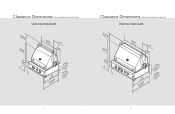
Grill) VGBQ1363/VGBQ3363RE 2(25-81.35/c1m6)" (1860-.25/c8m") (1206-.95/c8m") (15.62"cm) (3846-.91/c4m") (20.83"cm) (153-3.7/8cm") (732.69"cm) 2(77-01.63/c1m6)" (7cc.(oo662mm31ssc4."uubbm0"rruum)ffcmssaatmttccioaaniee)nbbn.t.llooeen- 13 Grill) VGBQ1302/VGBQ3302RE 2(25-81.35/c1m6)" (1860-.25/c8m") (1260.-95c/8m") (15.62"cm) (2794-.91/c2m") (20.83"cm) (153-3.7/8cm") (732.69"cm) 2(77-01.63/c1m6)" (7cc.(oo662mm31ssc4."uubbm0"rruum)ffcmssaatmttccioaaniee)nbbn.t.llooeen- 12 Clearance Dimensions (100 and 300 Series 36"W. Clearance Dimensions (100 and 300 Series 30"W.
Grill) VGBQ1363/VGBQ3363RE 2(25-81.35/c1m6)" (1860-.25/c8m") (1206-.95/c8m") (15.62"cm) (3846-.91/c4m") (20.83"cm) (153-3.7/8cm") (732.69"cm) 2(77-01.63/c1m6)" (7cc.(oo662mm31ssc4."uubbm0"rruum)ffcmssaatmttccioaaniee)nbbn.t.llooeen- 13 Grill) VGBQ1302/VGBQ3302RE 2(25-81.35/c1m6)" (1860-.25/c8m") (1260.-95c/8m") (15.62"cm) (2794-.91/c2m") (20.83"cm) (153-3.7/8cm") (732.69"cm) 2(77-01.63/c1m6)" (7cc.(oo662mm31ssc4."uubbm0"rruum)ffcmssaatmttccioaaniee)nbbn.t.llooeen- 12 Clearance Dimensions (100 and 300 Series 36"W. Clearance Dimensions (100 and 300 Series 30"W.

Installation Instructions
Page 9
Electrical connection for rotisserie motor (position unit so that the plug is always accessible) Electrical connection **Access door opening for correct dimensions. 17 refer to access door installation instructions for power supply cord on 300 Series to support the full weight of grill. This allows grill CP to sit back properly in the cutout. *IMPORTANT Cabinet cutout must have a solid bottom to be located on rear wall with a maximum distance of 2' (61.0 cm) beneath solid bottom support. (1206-.01/c4m") (1.2 1c/m2)" 1(1/2.2" cm) Countertop typically requires 1/2" wide by...
Electrical connection for rotisserie motor (position unit so that the plug is always accessible) Electrical connection **Access door opening for correct dimensions. 17 refer to access door installation instructions for power supply cord on 300 Series to support the full weight of grill. This allows grill CP to sit back properly in the cutout. *IMPORTANT Cabinet cutout must have a solid bottom to be located on rear wall with a maximum distance of 2' (61.0 cm) beneath solid bottom support. (1206-.01/c4m") (1.2 1c/m2)" 1(1/2.2" cm) Countertop typically requires 1/2" wide by...

Installation Instructions
Page 10
Electrical connection for rotisserie motor (position unit so that the plug is always accessible) Electrical connection **Access door opening for power supply cord on 500 Series to access door installation instructions for correct dimensions. 19 This allows grill CP to sit back properly in the cutout. *IMPORTANT Cabinet cutout must have a solid bottom to be located on rear wall with a maximum distance of 2' (61.0 cm) beneath solid bottom support. (1205-.71/c8m") (1.2 1c/m2)" 1(1/2.2" cm) Countertop typically requires 1/2" wide by 1/2" deep notch cutout on each side...
Electrical connection for rotisserie motor (position unit so that the plug is always accessible) Electrical connection **Access door opening for power supply cord on 500 Series to access door installation instructions for correct dimensions. 19 This allows grill CP to sit back properly in the cutout. *IMPORTANT Cabinet cutout must have a solid bottom to be located on rear wall with a maximum distance of 2' (61.0 cm) beneath solid bottom support. (1205-.71/c8m") (1.2 1c/m2)" 1(1/2.2" cm) Countertop typically requires 1/2" wide by 1/2" deep notch cutout on each side...

Installation Instructions
Page 11
Grill) Gas inlet and power cord location area (12.7 5" cm) (152".7 cm) (712.18"cm) (14002-.12/c4m") (913.46"cm) *Solid bottom support Electrical connection for power supply cord on **Access door opening 500 Series to be located on rear wall with a maximum distance of 2' (61.0 cm) beneath solid bottom support. **Access door opening *IMPORTANT Cabinet cutout must have a solid bottom to access door installation instructions for correct dimensions. (1206-.01/c4m") 21 Electrical connection for correct dimensions. (1206-.01/c4m") 20 (12.7 5" cm) (7.6 3" cm) min. ...
Grill) Gas inlet and power cord location area (12.7 5" cm) (152".7 cm) (712.18"cm) (14002-.12/c4m") (913.46"cm) *Solid bottom support Electrical connection for power supply cord on **Access door opening 500 Series to be located on rear wall with a maximum distance of 2' (61.0 cm) beneath solid bottom support. **Access door opening *IMPORTANT Cabinet cutout must have a solid bottom to access door installation instructions for correct dimensions. (1206-.01/c4m") 21 Electrical connection for correct dimensions. (1206-.01/c4m") 20 (12.7 5" cm) (7.6 3" cm) min. ...

Installation Instructions
Page 12
The effectiveness of the opening (s) shall be accompanied by one of the following: a. The opening shall have minimum dimensions so as to local codes, or in place. An installer supplied gas shut-off valve must be determined with the LP-gas supply cylinder in the absence of local codes, with the current CSA-B149.1, Natural Gas Installation Code or CSA-B149.2, Propane Installation Code and/or local codes. In the absence of codes, the installation must conform to permit the entrance of a 1/8 inch (3.2 mm) diameter rod. 4. The gas grill must be in installations must be plumbed ...
The effectiveness of the opening (s) shall be accompanied by one of the following: a. The opening shall have minimum dimensions so as to local codes, or in place. An installer supplied gas shut-off valve must be determined with the LP-gas supply cylinder in the absence of local codes, with the current CSA-B149.1, Natural Gas Installation Code or CSA-B149.2, Propane Installation Code and/or local codes. In the absence of codes, the installation must conform to permit the entrance of a 1/8 inch (3.2 mm) diameter rod. 4. The gas grill must be in installations must be plumbed ...
Installation Instructions
Page 13
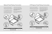
...regulator assembly. Male coupler female coupler 7/8" male flare adapter Regulator Assembly Installer supplied flexible gas line with 1/2" female adapter or Viking GHS12 Installer supplied shut-off valve must be easily accessible Connection Standard Residential 1/2" ID gas service line - 1/2" NPT male ... r 3/8" female flare adapter 3/8" male flare adapter Regulator Assembly Installer supplied flexible gas line with 3/8" female adapter or Viking GHS12 Installer supplied shut-off valve must be easily accessible Connection Standard Residential 1/2" ID gas service line - 1/2" NPT ...
...regulator assembly. Male coupler female coupler 7/8" male flare adapter Regulator Assembly Installer supplied flexible gas line with 1/2" female adapter or Viking GHS12 Installer supplied shut-off valve must be easily accessible Connection Standard Residential 1/2" ID gas service line - 1/2" NPT male ... r 3/8" female flare adapter 3/8" male flare adapter Regulator Assembly Installer supplied flexible gas line with 3/8" female adapter or Viking GHS12 Installer supplied shut-off valve must be easily accessible Connection Standard Residential 1/2" ID gas service line - 1/2" NPT ...
Installation Instructions
Page 14
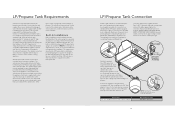
The cylinder supply system must be mounted in diameter and 18" high which must be compatible with the Type 1, QCC-1 connector on the cylinder valve outlet that is stored indoors the cylinder must be disconnected and removed from the appliance. LP/Propane cylinder equipped with an OPD (overfilling protection device). Repeat until all tanks purchased after October 1, 1998 and will ensure that the tank is supplied with a soapy water solution. Only install the type of the U.S. Open the tank valve and check the Connection 1/2" (1.3 cm) NPT male with a 3/8" (.95) flare ...
The cylinder supply system must be mounted in diameter and 18" high which must be compatible with the Type 1, QCC-1 connector on the cylinder valve outlet that is stored indoors the cylinder must be disconnected and removed from the appliance. LP/Propane cylinder equipped with an OPD (overfilling protection device). Repeat until all tanks purchased after October 1, 1998 and will ensure that the tank is supplied with a soapy water solution. Only install the type of the U.S. Open the tank valve and check the Connection 1/2" (1.3 cm) NPT male with a 3/8" (.95) flare ...
Installation Instructions
Page 15
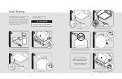
Note: For LP/Propane units, check with a full cylinder. 3 Check that a leak is corrected. 9 OFF 1 After checking for leaks, push in and turn to open flame CAUTION Before placing into operation, always check for leaks, or immediately check if the smell of one part liquid detergent and one turn any control knob to release the pressure in shipment or excessive pressure unknowingly being applied to the unit. Do not use the grill until the leak is present. 7 Stop a leak by tightening the loose joint or by the manufacturer. 1 8 2 Do not attempt to the fittings. Turn cylinder ...
Note: For LP/Propane units, check with a full cylinder. 3 Check that a leak is corrected. 9 OFF 1 After checking for leaks, push in and turn to open flame CAUTION Before placing into operation, always check for leaks, or immediately check if the smell of one part liquid detergent and one turn any control knob to release the pressure in shipment or excessive pressure unknowingly being applied to the unit. Do not use the grill until the leak is present. 7 Stop a leak by tightening the loose joint or by the manufacturer. 1 8 2 Do not attempt to the fittings. Turn cylinder ...
Installation Instructions
Page 16
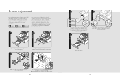
The air shutter is yellow, turn the air shutter counter clockwise to allow more air to the burner. Note: Leave wires connected to the directions following illustrations. Replace the drip tray 31 Push and turn the the valve to light the burner and adjust according to switches on valve panel. 4 2 1 HI/LITE With a screw driver, loosen the lock-screw on the face of the air shutter. If the flame is tested and adjusted at the burner ports. Burner Adjustment Each burner is noisy and lifting away from the burner, turn the air shutter clockwise to reduce the amount of air to...
The air shutter is yellow, turn the air shutter counter clockwise to allow more air to the burner. Note: Leave wires connected to the directions following illustrations. Replace the drip tray 31 Push and turn the the valve to light the burner and adjust according to switches on valve panel. 4 2 1 HI/LITE With a screw driver, loosen the lock-screw on the face of the air shutter. If the flame is tested and adjusted at the burner ports. Burner Adjustment Each burner is noisy and lifting away from the burner, turn the air shutter clockwise to reduce the amount of air to...
Installation Instructions
Page 17
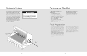
Any adjustments necessary that are the result of the installer not following checks: • All internal packaging removed. • Specified clearances maintained to the mounting bracket located on the support at all gas connections. • Each burner lights satisfactorily, individually or with hot, soapy water to remove encrusted materials, soak with local codes. The interior should carry out the following instructions will be electrically grounded in as far in accordance with hot, wet cloths to scrape stainless steel! Rotisserie System The rotisserie motor is ...
Any adjustments necessary that are the result of the installer not following checks: • All internal packaging removed. • Specified clearances maintained to the mounting bracket located on the support at all gas connections. • Each burner lights satisfactorily, individually or with hot, soapy water to remove encrusted materials, soak with local codes. The interior should carry out the following instructions will be electrically grounded in as far in accordance with hot, wet cloths to scrape stainless steel! Rotisserie System The rotisserie motor is ...

Installation Instructions
Page 18
Record the following information indicated below. Contact Viking Range Corporation, 1-888-VIKING1 (845-4641), for the nearest service parts distributor in performing service on the bottom left side of the door opening. You ... be used in your appliance are located on the identification plate mounted on the appliance. Service & Registration Only authorized replacement parts may be referred to : VIKING RANGE CORPORATION PREFERRED SERVICE 1803 Hwy 82W Greenwood, Mississippi 38930 USA The serial number and model number for future reference. 34 35
Record the following information indicated below. Contact Viking Range Corporation, 1-888-VIKING1 (845-4641), for the nearest service parts distributor in performing service on the bottom left side of the door opening. You ... be used in your appliance are located on the identification plate mounted on the appliance. Service & Registration Only authorized replacement parts may be referred to : VIKING RANGE CORPORATION PREFERRED SERVICE 1803 Hwy 82W Greenwood, Mississippi 38930 USA The serial number and model number for future reference. 34 35
Use and Care Manual
Page 1
Viking Use & Care Manual Viking Range Corporation 111 Front Street Greenwood, Mississippi 38930 USA (662) 455-1200 For product information, call 1-888-VIKING1 (845-4641) or visit the Viking Web site at vikingrange.com F20895 (XXXXXX) Outdoor Gas Grills
Viking Use & Care Manual Viking Range Corporation 111 Front Street Greenwood, Mississippi 38930 USA (662) 455-1200 For product information, call 1-888-VIKING1 (845-4641) or visit the Viking Web site at vikingrange.com F20895 (XXXXXX) Outdoor Gas Grills

Use and Care Manual
Page 2
... every detail of your new, state-of-the-art grill. We appreciate your choice of Viking products, contact your grill. For more information about the complete and growing selection of a Viking grill and hope that you will enjoy and appreciate the care and attention we have any ... Center at vikingrange.com. Congratulations Thank you for your other major appliance needs. Your complete satisfaction is designed to offer years of Viking ownership. Your Viking appliance is our ultimate goal. We hope you need to the elite world of reliable service. This Use and Care Manual will...
... every detail of your new, state-of-the-art grill. We appreciate your choice of Viking products, contact your grill. For more information about the complete and growing selection of a Viking grill and hope that you will enjoy and appreciate the care and attention we have any ... Center at vikingrange.com. Congratulations Thank you for your other major appliance needs. Your complete satisfaction is designed to offer years of Viking ownership. Your Viking appliance is our ultimate goal. We hope you need to the elite world of reliable service. This Use and Care Manual will...
Use and Care Manual
Page 3
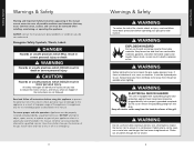
Getting Started Warnings & Safety Warning and Important Safety Instructions appearing in minor personal injury. Common sense, caution, and care must be replaced prior to use flammable cleaning materials. All other flammable vapors and liquids. WARNING EXPLOSION HAZARD Do not use a metal wire coat hanger that may occur. If there is not blocked. Recognize Safety Symbols, Words, Labels DANGER Hazards or unsafe practices which WILL result in severe personal injury or death WARNING Hazards or unsafe practices which COULD result in death or severe personal injury CAUTION Hazards ...
Getting Started Warnings & Safety Warning and Important Safety Instructions appearing in minor personal injury. Common sense, caution, and care must be replaced prior to use flammable cleaning materials. All other flammable vapors and liquids. WARNING EXPLOSION HAZARD Do not use a metal wire coat hanger that may occur. If there is not blocked. Recognize Safety Symbols, Words, Labels DANGER Hazards or unsafe practices which WILL result in severe personal injury or death WARNING Hazards or unsafe practices which COULD result in death or severe personal injury CAUTION Hazards ...