
English Manual
Page 13
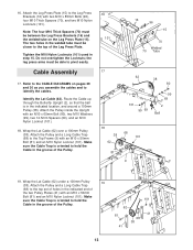
... the Upright with two M10 x 85mm Bolts (96), four M10 Thick Spacers (70), and two M10 Nylon Locknuts (101). Attach the Pulley and a Long Cable Trap (68) to the CABLE DIAGRAMS on the Leg Press Plate (15). Do not overtighten the Locknuts; Refer to the top set of the Leg Press Plate.... Make sure the Cable Trap is oriented to the Top Frame (9) with an M10 x 50mm Bolt (81) and an M10 Nylon Locknut (101). Attach the Pulley and a Long...
... the Upright with two M10 x 85mm Bolts (96), four M10 Thick Spacers (70), and two M10 Nylon Locknuts (101). Attach the Pulley and a Long Cable Trap (68) to the CABLE DIAGRAMS on the Leg Press Plate (15). Do not overtighten the Locknuts; Refer to the top set of the Leg Press Plate.... Make sure the Cable Trap is oriented to the Top Frame (9) with an M10 x 50mm Bolt (81) and an M10 Nylon Locknut (101). Attach the Pulley and a Long...
English Manual
Page 25
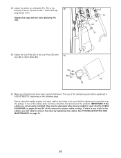
The use of the cables does not move smoothly over the pulleys. See TROUBLESHOOTING AND MAINTENANCE on pages 29 and 30 of this step with an M4 x 15mm Self-tap- Before using the weight system, pull each ..., beginning on a Butterfly Pin (78) to the Curl Post (28) with 66 four M6 x 16mm Bolts (89). 89 89 29 28 67. See the CABLE DIAGRAMS on page 31. 25 Make sure that the cables move smoothly, find and correct the problem. ping Screw (107). Repeat this manual for proper cable...
The use of the cables does not move smoothly over the pulleys. See TROUBLESHOOTING AND MAINTENANCE on pages 29 and 30 of this step with an M4 x 15mm Self-tap- Before using the weight system, pull each ..., beginning on a Butterfly Pin (78) to the Curl Post (28) with 66 four M6 x 16mm Bolts (89). 89 89 29 28 67. See the CABLE DIAGRAMS on page 31. 25 Make sure that the cables move smoothly, find and correct the problem. ping Screw (107). Repeat this manual for proper cable...


