

English Manual
Page 11
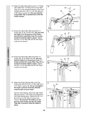
... Locknuts (3). Attach the Pulley to turn freely. 17 17. Locate and open the parts bags labeled "CABLE ASSEMBLY" and "PULLEYS." 16 During steps 16 through 36, refer to the CABLE DIAGRAMS on the indicated side of the Pulley and that the end of this section, fully unwind the... VKR Upright (74) with a 3/8" x 3 3/4" Bolt (88) and a 3/8" Nylon Locknut (21). Wrap the High 21 Cable around a 3 1/2" Pulley (15). Attach the Military Press Arm (84) to verify proper cable routing. Attach the Military 15 Press Arm (84) to the Pivot Arm (101) with the ball is listed (in inches...
... Locknuts (3). Attach the Pulley to turn freely. 17 17. Locate and open the parts bags labeled "CABLE ASSEMBLY" and "PULLEYS." 16 During steps 16 through 36, refer to the CABLE DIAGRAMS on the indicated side of the Pulley and that the end of this section, fully unwind the... VKR Upright (74) with a 3/8" x 3 3/4" Bolt (88) and a 3/8" Nylon Locknut (21). Wrap the High 21 Cable around a 3 1/2" Pulley (15). Attach the Military Press Arm (84) to verify proper cable routing. Attach the Military 15 Press Arm (84) to the Pivot Arm (101) with the ball is listed (in inches...
English Manual
Page 12
...inset drawing. Tighten the 3/8" x 2" 20 12 Bolt (12) and a 3/8" Nylon Locknut (not shown). Route the High Cable (58) around the 3 1/2" Pulley (15) attached to hold the Cable in place. 18. Be sure that the Cable 3 15 58 Trap (66) is turned to the indicated bracket on the Right Arm (48). Attach... the Pulley Bracket (20) to move freely. Route the High Cable 55 66 (58) around the "V"- 20 Pulley (50) on the Front Upright (42) with the 5/16" x 5" Bolt (68) and a 68 5/16" Nylon ...
...inset drawing. Tighten the 3/8" x 2" 20 12 Bolt (12) and a 3/8" Nylon Locknut (not shown). Route the High Cable (58) around the 3 1/2" Pulley (15) attached to hold the Cable in place. 18. Be sure that the Cable 3 15 58 Trap (66) is turned to the indicated bracket on the Right Arm (48). Attach... the Pulley Bracket (20) to move freely. Route the High Cable 55 66 (58) around the "V"- 20 Pulley (50) on the Front Upright (42) with the 5/16" x 5" Bolt (68) and a 68 5/16" Nylon ...
English Manual
Page 13
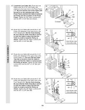
...55) with a 3/8" x 2" Bolt (12) and a 3/8" Nylon Locknut (21). Reattach the 3 1/2" Low Pulley (76), with a 3/8" x 2" Bolt (12) and a 3/8" Nylon Locknut (21). Route the High Cable (58) through the Long "U"-Bracket (57) and the 3 1/2" Pulley (15) shown in the groove of the Pulley and that the...tighten the 3/8" Nylon Locknut (21) yet. See the inset drawing. 22. The Bolt has been shown removed for shipping purposes. Be sure that the Cable Trap is inside the Long "U"Bracket. Note: This may come pre-assembled. Remove the 3/8" Nylon Locknut (21), the Spacer, and the Pulley from the...
...55) with a 3/8" x 2" Bolt (12) and a 3/8" Nylon Locknut (21). Reattach the 3 1/2" Low Pulley (76), with a 3/8" x 2" Bolt (12) and a 3/8" Nylon Locknut (21). Route the High Cable (58) through the Long "U"-Bracket (57) and the 3 1/2" Pulley (15) shown in the groove of the Pulley and that the...tighten the 3/8" Nylon Locknut (21) yet. See the inset drawing. 22. The Bolt has been shown removed for shipping purposes. Be sure that the Cable Trap is inside the Long "U"Bracket. Note: This may come pre-assembled. Remove the 3/8" Nylon Locknut (21), the Spacer, and the Pulley from the...
English Manual
Page 14
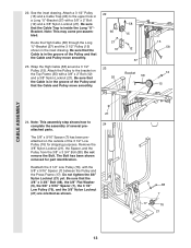
...23 15 21 66 17 28. Be sure that the Cable Trap (66) is turned to hold the Cable in place and that the Cable is routed around the 3 1/2" Pulley (15) attached to hold the Cable in place and that the Cable is routed around the Pulley as shown. Tighten the 3/8" Nylon ... (21) and the 3/8" x 3 3/4" Bolt (not shown). Route the Low Cable (23) around the Pulley as shown. Route the Low Cable (23) around the 3 1/2" Pulley (15) attached to the upper hole in the Front Upright (42). CABLE ASSEMBLY 25. Route the Low Cable (23) around the 3 1/2" 28 Pulley (15) attached to the...
...23 15 21 66 17 28. Be sure that the Cable Trap (66) is turned to hold the Cable in place and that the Cable is routed around the 3 1/2" Pulley (15) attached to hold the Cable in place and that the Cable is routed around the Pulley as shown. Tighten the 3/8" Nylon ... (21) and the 3/8" x 3 3/4" Bolt (not shown). Route the Low Cable (23) around the Pulley as shown. Route the Low Cable (23) around the 3 1/2" Pulley (15) attached to the upper hole in the Front Upright (42). CABLE ASSEMBLY 25. Route the Low Cable (23) around the 3 1/2" 28 Pulley (15) attached to the...

English Manual
Page 17
...and a 3/8" Nylon Locknut (21). Locate the Leg Press Cable (99). Attach the 35 end of the Pulley and that the Cable is in the inset drawing. Bracket (57) with a 1/4" Nylon Locknut (2) and a 1/4" Flat Washer (10). assembled.) Route the Military Press Cable (72) through the Pivot Arm (101) from the ...indicated side. Be sure that the Cable and Pulley move smoothly and that the Cable Trap is between the two Jam Nuts for the end of turns, as...
...and a 3/8" Nylon Locknut (21). Locate the Leg Press Cable (99). Attach the 35 end of the Pulley and that the Cable is in the inset drawing. Bracket (57) with a 1/4" Nylon Locknut (2) and a 1/4" Flat Washer (10). assembled.) Route the Military Press Cable (72) through the Pivot Arm (101) from the ...indicated side. Be sure that the Cable and Pulley move smoothly and that the Cable Trap is between the two Jam Nuts for the end of turns, as...

English Manual
Page 21
... it to the Front Upright (42) under the "WEIDER" nameplate as shown. 46 WEIDER Nameplate 42 PRO 9635 Decal 47. If one of this manual. If there is used. See TROUBLESHOOTING AND MAINTENANCE on page 26 and 27 of the cables does not move smoothly over the pulleys. Make sure ... IMPORTANT: If the cables are not properly installed, they may be sure that all parts have been properly tightened. Remove the adhesive backing from the PRO 9635 decal and apply it by tightening the cables. See the CABLE DIAGRAMS on page 25. 21 46. The use of this manual for proper cable routing.
... it to the Front Upright (42) under the "WEIDER" nameplate as shown. 46 WEIDER Nameplate 42 PRO 9635 Decal 47. If one of this manual. If there is used. See TROUBLESHOOTING AND MAINTENANCE on page 26 and 27 of the cables does not move smoothly over the pulleys. Make sure ... IMPORTANT: If the cables are not properly installed, they may be sure that all parts have been properly tightened. Remove the adhesive backing from the PRO 9635 decal and apply it by tightening the cables. See the CABLE DIAGRAMS on page 25. 21 46. The use of this manual for proper cable routing.

English Manual
Page 26
... on these pages show the proper positioning of the High Cable (58), the Low Cable (23), the Military Press Cable (72), and the Leg Press Cable (99). The cable traps should be sure that the four cables and the cable traps have not been correctly routed, the home gym system will not come off the pulleys. If the...
... on these pages show the proper positioning of the High Cable (58), the Low Cable (23), the Military Press Cable (72), and the Leg Press Cable (99). The cable traps should be sure that the four cables and the cable traps have not been correctly routed, the home gym system will not come off the pulleys. If the...


